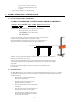
Color VISUAL HEADLAMP ALIGNMENT SYSTEM With: Visual Assist Meter VISUAL ASSIST HIGH BEAM LOW BEAM ASSEMBLY OPERATION CALIBRATION 524 S. E. Transport Drive Lee's Summit, MO 64081 888-884-8182 816-525-9263 FAX: 816-525-9283 www.symtechcorp.
INDEX 1. GENERAL Pg. 3 1.1 1.2 1.3 1.4 1.5 CVA 3 EZ ISOColor INTRODUCTION SYSTEM COMPONENTS LASER WARNING VISUAL ASSIST METER & SWITCH ISOColor LAMP PATTERN DEFINITION 2. ASSEMBLY Pg. 4 2.1 2.2 2.3 2.4 2.5 2.6 BASE / WHEEL ATTACHMENT MAST / GLIDE PLATE / ROTATIONAL MAST MOUNT OPTICAL ALIGNMENT HEAD VEHICLE ALIGNMENT MIRROR ALIGNMENT MIRROR CALIBRATION FLOOR SLOPE LASER 3. OPERATION Pg. 6 3.1 ALIGNMENT BAY(s) PREPARATION 3.2 FLOOR SLOPE MEASUREMENT 3.3 VEHICLE PREPARATION, Prior to Alignment 4.
1. GENERAL 1.1 INTRODUCTION The Model CVA 3 EZ ISOColor Visual Headlamp Alignment System is an economical optical alignment tool that functions under the same principle for accuracy and dependability of an aiming screen, with the added benefit of Color Defined Lamp Pattern and a Visual Assist meter, without the excessive use of valuable shop space and the confusion of vertical and horizontal lamp placement. System design and operation has been engineered with the technician in mind.
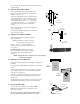
1.4 VISUAL ASSIST METER & SWITCH The Visual Assist meter is an aide for positioning the headlamp pattern to its correctly designed position. While visually adjusting the headlamp into position, the Visual Assist meter will raise in numeric reading if adjustment is directed in the correct direction. Adversely, the meter reading will decrease if headlamp is adjusted in the incorrect direction.
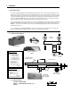
Move glide plate up and down the mast through its full motion, by depressing handle. 2.3 OPTICAL ALIGNMENT HEAD Remove optical alignment head from shipping carton. Inspect for any damage that may have occurred during shipment i.e. lens, case, etc.. Attach optical alignment head to the mast glide plate by aligning mounting holes of glide plate with the holes in the optical head.
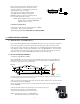
Remove floor slope laser from packaging and insert front fixture placement pin into hole on top and at rear of the optical head, also there is an indentation provided for the height adjustment screw to rest within. Activate the laser by turning front knob clockwise (CAUTION: Excessive turning may damage laser ON/OFF mechanism) to assure of functionality, turn off laser. No further adjustment is required.
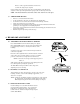
wheels, to achieve equal measurements, more than one eccentric axle change may be required. Note the number on the floor slope gauge and record that number along with the bay designate on floor slope sticker provided. Repeat procedure for other bays and record. NOTE: After measurements have been taken, remove laser and store in a secure place 3.3 VEHICLE PREPARATION • • • • • • • Remove ice or mud from under the fenders. Set the tire inflation to the values recommended by the manufacturer.
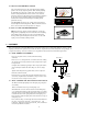
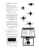
• • • • • SAE HIGH BEAM: All high beam lamps. Highest intensity point is centered on the Horizontal / Vertical axis. SAE LOW BEAM: All low beam lamps manufactured prior to 1999. After 1999, some vehicles could have headlamp patterns that are VOR or VOL . The high intensity area is located in the lower right hand quadrant. H V H FOG LAMPS: All fog lamps the top of the high intensity area is located 4 down and centered on the Vertical axis.
denotes 8 inches, inner box denotes 4 inches. Each hash mark denotes 1 inch increment. • Repeat steps 2 through 4 for remaining lamps. 6. LASER CALIBRATION / MAINTENANCE 5.
6. FREQUENTLY ASKED QUESTIONS Question: Level in optical head is not centered during alignment procedure? Answer: Level vial is used ONLY when checking the calibration of the floor slope laser. Question: The high intensity (hot spot) area of the headlamp how is this determine? Answer: All lamps are legislated to be created equal, but this has proven not to be the case. The CVA 3EZ ISOColor incorporates color definition technology that defines the high intensity zone for ease of alignment.
WARRANTY All Symtech Corporation products are warranted to be free from defects in material and workmanship under normal user service for a period of one year after the sale of the product. Exception to this policy will be individually evaluated and must be approved by Symtech Corporate. The sole obligation under this warranty shall be to repair, or replace any defective products or parts thereof, which upon examination are deemed to the seller s satisfaction to be defective.