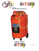
Safety by Design OPERATION MANUAL Radiator Coolant Service Center Revision: 06/12/12
Table of Contents Introduction………………………………………………………………………………………………….2 Safety Precautions……………………………………………………………………………………………3 System Functional Components…………………………………………………………………………….4 Before Starting………………………………………………………………………………………………4-5 Control Panel Descriptions and Functions………………………………………………………………...7 Pressure Relief Procedure…………………………………………………………………………………..7 Drain and Fill versus Reverse Flush……………………………………………………………………….8 DRAIN AND FILL EXCHANGE Draining Cooling System .............................
Introduction Thank you for purchasing Symtech Corporation’s VFX 1 Radiator Coolant Service System. The VFX 1 is a very simple yet effective machine design to quickly perform all required periodic maintenance services for automotive cooling systems. It is extremely easy to operate, environmentally safe, and designed for the greatest speed and efficiency. The Operations Manual MUST be read and COMPLETELY UNDERSTOOD in order to properly operate the unit and experience the highest return on investment.
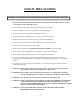
SAFETY PRECAUTIONS WARNING: FAILURE TO FOLLOW PRECAUTIONS CAN RESULT IN INJURY OR DEATH Always use extreme caution and forethought when servicing automotive systems! Automotive systems are extremely hot and contain high pressure. Always read and understand the entire Operations Manual before operating! Always wear proper eye and skin protection when operating equipment! Always keep fire extinguisher nearby for flammable conditions! Always keep hair, loose clothing, hoses, etc.
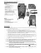
VFX 1 System Functional Components FRONT: 1. CONTROL PANEL 2 1A. AIR CONTROL VALVE 1B. FUNCTION CONTROL VALVE 3 1C. FLUID CONTROL VALVE 2. PRESSURE GAUGE 3. NEW FLUID FILL CAP 4. NEW FLUID TANK SELECTOR 5. NEW AND USED FLUID HOSES 6. NEW FLUID ALTERNATE TANK CONNECTION 7. NEW FLUID ALTERNATE TANK 8. EXTRACTION PORT, TOOL STORAGE COMPARTMENT DRAIN RESERVOIR. 9. RED/ NEW COOLANT FLOW CONTROL VALVE 10. BLACK/USED COOLANT FLOW CONTROL VALVE 11.
Control Panel Descriptions and Functions The following information is intended to familiarize the VFX 1 operator with the control panel and its functions. Time must be taken to read and understand the VFX 1 controls and operation for safe and acceptable performance of the unit. All control panel valve functions are color coded to aid technician in the function selection process. Simply match all three control panel valves to the matching colored function legends at each control panel valve - #1, #2, and #3.
FLUSH (BLUE), DRAIN AND FILL (RED) , LOWER LEVEL (YELLOW) , – This position diverts generated vacuum to the used coolant tank where it is stored, allowing the user to extract used coolant from vehicle during the DRAIN & FILL and LOWER LEVEL procedures. This position also prevents pressure build up in used fluid tank during FLUSH procedure. EMPTY USED (PURPLE) – This position allows internally regulated air pressure to build in used fluid tank to ultimately force used coolant from the used fluid tank.
FLOW CONTROL VALVES The flow control valves at the end of the RED/NEW and BLACK/USED hose ends should always be in the closed position until desired function is ready to be performed. This prevents accidental operation or spills until technician is ready to remove and/or add coolant.
DRAIN and FILL (RED) versus REVERSE FLUSH (BLUE) The VFX 1 Coolant exchange system offers two methods to easily perform coolant exchanges: DRAIN AND FILL (RED) and REVERSE FLUSH (BLUE). The following information describes the basic differences between the two types, and the advantages and disadvantages of each. DRAIN AND FILL (RED) - entails using shop air pressure to create vacuum in the VFX 1.
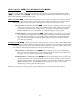
DRAIN AND FILL EXCHANGE (RED ) Draining Cooling System NOTE: The RED/NEW coolant hose is not used to perform a DRAIN AND FILL (RED) coolant exchange. 1) Verify Pressure Relief Procedure described above has been performed. 2) Verify adequate capacity for used fluid with used fluid sight gauge. Refer to EMPTY USED coolant section to empty used coolant tank.
Vacuum Leak Testing Cooling System (This test can only be performed on cool engines) While the cooling system is in a “trapped vacuum condition” from the Draining Cooling System procedure above, the vacuum level can be recorded and checked over a period of time, usually two minutes. If the vacuum level decreases, there may be a leak in the cooling system.
REVERSE FLUSH EXCHANGE (BLUE ) NOTE: Before Starting, Control Panel Descriptions and Functions must be read and understood.
flow control valve connected to the upper radiator hose adapter and the BLACK/USED flow control valve connected to the engine block outlet adapter. The vehicle is started and allowed to reach normal operating temperature which allows the thermostat to open allowing coolant to flow from the unit through the cooling system and back into the unit.
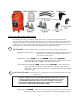
ADAPTER SET-UP 1) Disconnect the upper radiator hose at most accessible point. 2) The appropriate size adapter hose along with its matching step adapter is installed on the exposed outlet neck and secured with correct hose clamps. 3) The tightest fitting step adapter is next installed and secured by hose clamps to the vehicle’s exposed radiator hose making sure the connection plugs are accessible.
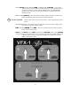
DISCONNECTING (YELLOW) To minimize spillage from disconnecting the unit from the vehicle the coolant level needs to be lowered again using the LOWER LEVEL (YELLOW) procedures: 1) Verify adequate capacity for used fluid in used fluid sight gauge. Refer to EMPTY USED coolant section to empty used coolant tank. Figure 1 2) Verify that all VFX 1 Control panel valves are in the neutral position, (Fig 1) and flow control valves at hose ends are off.
Changeover of PRIMARY (internal) Coolant Tank to ALTERNATE (external) Coolant Tank The VFX 1 can be used with multiple coolant types by simply switching between the PRIMARY (internal) Fluid Tank and an ALTERNATE (external) Fluid Tank. The VFX 1 comes with one additional ALTERNATE (external) Fluid Tank. Additional tanks can be purchased through Symtech Corporation or one of its Distributors. Inquire for a Distributor location nearest you.
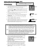
Changeover of ALTERNATE (external) Coolant Tank to PRIMARY (internal) Coolant Tank 1) Verify all control panel valves are in neutral position, (Fig 1) and flow control valves at hose ends are OFF. Figure 1 2) Connect to clean shop air (70-120psi). 3) Romove lid from ALTERNATE (external) coolant tank and connect to ALTERNATE (external) coolant tank hose. 4) Turn Coolant select valve to ALTERNATE (external) Coolant Tank.
Empty Used Coolant 1) Verify all control panel valves are in neutral position, and flow control valves at hose ends are OFF. Figure 1 2) Connect to clean shop air supply (70-120psi). 3) Turn AIR CONTROL valve (#1) and FUNCTION CONTROL valve (#2) to the left EMPTY USED (PURPLE) and FLUID CONTROL valve (#3) to the right, EMPTY USED (PURPLE). 4) Connect cone assembly to BLACK/USED coolant flow control valve at hose end. (Fig 3) Figure 2 5) Secure cone assembly into used coolant storage vessel.
Troubleshooting PROBLEM Vacuum speed or level is reduced SOLUTION - Inadequate air supply. Must maintain 70psi minimum throughout service. - Air powered vacuum venturi has become clogged with debris from dirty air supply. Please contact Symtech for service procedures. - Leak in the unit. Please contact Symtech Corporation for service procedures.
WARRANTY STATEMENT All Symtech Corporation Coolant Service products are warranted to be free from defects in material and workmanship under normal use and service for a period of one year from time of purchase. Adapters and fittings are warranted for a period of ninety (90) days. Exception to this policy will be individually evaluated and must be approved by Symtech Corporate.