
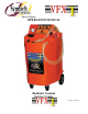
User Manual

4
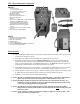
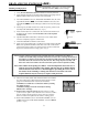
VFX 1 System Functional Components
FRONT:
1. CONTROL PANEL
1A. AIR CONTROL VALVE
1B. FUNCTION CONTROL VALVE
1C. FLUID CONTROL VALVE
2. PRESSURE GAUGE
3. NEW FLUID FILL CAP
4. NEW FLUID TANK SELECTOR
5. NEW AND USED FLUID
HOSES
6. NEW FLUID ALTERNATE TANK CONNECTION
7. NEW FLUID ALTERNATE TANK
8. EXTRACTION PORT, TOOL STORAGE
COMPARTMENT DRAIN RESERVOIR.
9. RED/ NEW COOLANT FLOW CONTROL
VALVE
10. BLACK/USED COOLANT FLOW CONTROL
VALVE
11. TOOL STORAGE COMPARTMENT
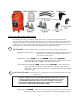
REAR:
1. NEW FLUID TANK SIGHT GAUGE
2. USED FLUID TANK SIGHT GAUGE
3. SHOP AIR CONNECTION
4. INLINE FILTER
5. SERIAL NUMBER PLATE
6. 5 GALLON PRIMARY (INTERNAL) NEW FLUID TANK
7. 15 GALLON USED FLUID TANK
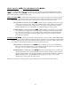
Before Starting
1) Upon unpacking the VFX 1 verify all components as depicted below are included. Contact Symtech if any
components are damaged or missing.
2) Thoroughly read manual and become familiar with control panel and components!
3) Prepare appropriate mixture of water and vehicle specified type of coolant in the new fluid container.
Always use specified coolant per vehicle manufacturer’s specification or vehicle owner’s manual. The
VFX 1 is shipped standard with “1”, PRIMARY (internal) and “1” ALTERNATE (external) 5-gallon new
coolant tanks. Additional tanks can be ordered from Symtech as required.
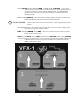
4) Verify that all valves are in the correct position – see information on control panel valves and verify flow
control valves located at hose ends are closed to avoid accidental operation or spills. (See Pg 5-7)
5) Connect the VFX 1 to clean shop air supply – minimum constant pressure of 70psi and maximum pressure
of 120psi. Shop air must be filtered clean air as debris may impact performance of the unit.
6) The VFX 1 is now ready to perform coolant fluid exchanges.
NOTE: NEVER over fill PRIMARY (internal) New Fluid Tank, doing so could cause a small amount of
fluid to seep out of the overflow tube, leaving traces of fluid in bottom of VFX 1 case.
NOTE: NEVER put anything but coolant and water mix in the new coolant tank of the VFX 1. If A
CHEMICAL cooling system flush is to be used, it should be added and circulated in the cooling
system prior to exchange functions being performed.
NOTE: NEVER put any type of STOP LEAK into New Fluid Tank, STOP LEAK will clog filters,
fittings and hoses. Placing STOP LEAK into the new fluid tank will VOID warranty and result
in excessive repairs.
NOTE: Always test the freeze point of coolant after exchange is complete to verify the coolant offers
proper protection for geographic area.
1
2
3
4
5
6
7
8
9
10
1A
1B
1C
2
1
3
4
5
6
7
11