
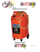
User Manual

7
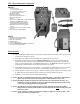
FLOW CONTROL VALVES
The flow control valves at the end of the RED/NEW and BLACK/USED
hose ends should always be in the closed position until desired function is
ready to be performed. This prevents accidental operation or spills until
technician is ready to remove and/or add coolant.
WARNING: HOSE CONNECTIONS AND FITTINGS CAN BECOME EXTREMELY HOT
DURING COOLANT FLUSH AND VACUUM DRAIN AND FILL OPERATIONS,
CAUTION MUST BE TAKEN WHEN HANDLING FITTINGS!! WEAR GLOVES
OR USE OTHER MEANS TO SHIELD AGAINST INJURY!!
CONTROL VALVE, PRIMARY (INTERNAL) / ALTERNATE (EXTERNAL)
NEW FLUID COOLANT TANK(S)
Coolant Tank Control Valve, switches between the PRIMARY
(internal) coolant tank and an ALTERNATE (external) coolant tank,
the OFF position is used only when servicing the PRIMARY (internal)
coolant filter.
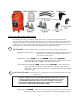
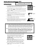
Pressure Relief Procedure
1) Verify adequate capacity for used fluid in used fluid sight gauge. Refer to
EMPTY USED coolant section to empty used coolant tank.
2) Properly secure vehicle against accidental movement.
3) Verify all VFX 1 Control panel valves are in the neutral position, AIR
CONTROL Valve #1, OFF, FUNCTION CONTROL Valve #2, HOLD, and
FLUID CONTROL Valve #3, OFF. (Fig 1)
4) Connect clean shop air supply (70-120psi).
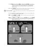
5) Turn AIR CONTROL valve (#1)
FUNCTION CONTROL valve (#2) and
FLUID CONTROL valve to the right, LOWER LEVEL (
YELLOW
).
(Fig 2) Vacuum will begin to build on the compound gauge.
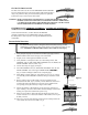
6) Insert rubber “pressure relief hose” into opening of cone. (Fig 3) Connect
cone assembly to BLACK/USED coolant hose and open used flow control
valve.
7) Remove cooling system overflow tube or hose from radiator neck or
Remote Reservoir tank, (Fig 4). Securely connect rubber hose extension to
overflow tube. Note: The rubber hose extension can be omitted and the
cone opening can be placed directly on large overflow tubes.
8) Slowly open radiator or Remote Reservoir cap observing vacuum level.
Upon “cracking” seal, used coolant will be extracted through overflow tube
creating a low pressure area behind the system’s cap.
9) When no used coolant is observed flowing through the clear hose and a
vacuum of at least 15” is reached, the radiator or Remote Reservoir cap can
be safely removed.
10) Once cap is removed return all control panel valves to neutral position and
flow control valves at hose ends OFF. (Fig 5)
The Pressure Relief procedure is designed to allow immediate servicing of “HOT
VEHICLES” by alleviating cooling system pressure versus waiting for vehicle to cool
down. EXTREME CARE must still be taken as hot coolant can cause injury.
Figure 1
Figure 5
Figure 4
Figure 2
Figure 3