
User Manual


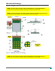
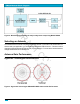

Table Of Contents

DRAFT COPY
Generated on
9/16/2014
Mechanical Drawings
Figure 1 and Figure 2 show the modules with the compact F antenna ad U.FL Connector options.
NOTE: The area under the module's antenna (marked KEEPOUTAREA)should have no
components, no traces, and no copper on any layer of the printed circuit board.
NOTE: For best performance, the module should be mounted on the outside edge of the circuit
board with the antenna side as close to the edge of the board as possible.
Figure 1: SM220UF1 Mechanical Drawing
NOTE: The area under the module's antenna (marked KEEPOUTAREA)should have no
components, no traces, and no copper on any layer of the printed circuit board.
7
SNAP Engine SM220 Series Data Sheet — 430000-01A