
User's Manual


SynapSense Installation and User Manual
Release 1
Page 7
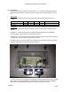
2.2 Connections
Unscrew and remove the clear lid from the device. The connections noted below should be
drawn through the available conduit connectors as shown in the outline drawings in section
2.1.
Power Input
AC or DC input power should be connected to the two-terminal block as labeled on the
product.
Parameter Min Typical Max Units Notes
AC Input 20.4 24 27.6 V
RMS
DC Input 20.4 24 27.6 V
To Actuator
Connections to the damper actuator are made to the four-terminal block as labeled on the
product.
Feedback In: A 0-10V analog input to the Wireless Damper Controller which should be
connected to the output control of a 0-10V damper actuator.
Feedback Out: A 0-10V analog output from the Wireless Damper Controller which should be
connected to the input control of a 0-10V damper actuator.
24V Out/Common: Power is provided to the damper actuator through the Wireless Damper
Controller and should be connected in this terminal block.
Once all connections are complete, the clear top lid should be replaced and screwed in tightly.
When using the provided watertight conduit connectors, the enclosure supports NEMA4X
certifications if properly tightened using the specified torque rating of 8 in-lbs.