
User's Manual

User Manual: Field Transmitter
PCU_User_Guide_1.3.0 8 © 2019 Syscor Controls & Automation Inc.
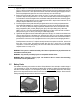
1) Apply two wraps of ¾” wide PTFE tape around the gland threads in the clockwise direction according to
Figure 10: Direct mounted PTFE tape application Remove the port plug if one is installed and screw the
gland into one of the two ½” NPT ports on the bottom of the PCU. Ensure the gland is tightly screwed to
the PCU expecting that the gland does not screw in all the way due to the PTFE tape.
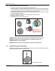
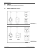
2) Prepare the sensor probe’s cable end as shown in Figure 12: Direct and remote sensor probe wire
preparation. Strip the outer jacket back 2” or 51mm, remove the fabric braid, foil and cloth wrapping. It is
recommended to cut the wire lengths at 5mm decrements starting with the white wire, followed by green,
shield, black and ending with the red wire. Strip the jackets 3mm to expose inner conductors. Do not
attempt to strip the shield wire as it has no jacket.
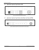
3) Feed the prepared sensor probe cable through a gland and into the PCU wiring compartment where
two terminal strips labelled Port 1 and Port 2 are located. If you have not yet removed the PCU outer
cover, do so and you will see the wiring compartment. Match the wires colors to the silkscreen of the
wiring compartment. [WHT] is white, [GRN] is green, [SIL] is silver (the shield), [BLK] is black and
[RED] is red. Port 1 and 2 have electrically identical ratings and you may connect an HCD or HCDW to
either port. See Figure 14: Sensor probe wiring for a final wiring solution.
4) Tighten the cable gland around the cable until the gland has a firm grip. You should see the rubber insert
compress and exit the tip of the gland a bit. Screw the PCU outer cover on the wiring compartment
ensuring a tight fit that won’t come off easily. Enclosure threads should be free of dirt and other debris to
prevent seizure of the outer cover. Only tighten the outer cover by hand to avoid damaging the device.
Field Replacement Instructions: To replace remotely mounted sensor probes on the PCU, unscrew the
PCU outer cover by hand. Then detach all cable wires from Port 1 and/or Port 2 of the wiring
compartment. Loosen the cable gland(s) and remove the cables from the interior of the PCU. Finally,
complete section 2.4.2 steps 1 to 4.
WARNING: This system is certified intrinsically safe. Sensor replacement may be performed in the
field without a hot work permit.
WARNING: Only sensors provided by Syscor are compatible with this device.
WARNING: When replacing a sensor, proper care should be taken to ensure that surrounding
environment is free of hydrocarbons.
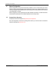
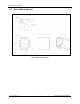
2.5 Battery Packs
The standard size battery pack contains two Lithium-Thionyl Chloride D size cells with a nominal voltage of
7.2V and ampacity of 19.0Ah. The extended size battery pack contains four Lithium-Thionyl Chloride D size
cells with a nominal voltage of 7.2V and ampacity of 38.0Ah. Do not recharge! Remove and store battery
packs at room temperature when the device is not in use to ensure optimal battery lifespan. Please read the
warnings regarding field replacement at the end of section 2.5.
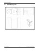
Figure 15: Standard size battery pack
Figure 16: Extended size battery pack