User Manual SysKonnect SK-98xx V2.
SysKonnect SK-98xx V2.0 Gigabit Ethernet Adapter User Manual (v2.10 17 February, 2003) Visit our web site: http://www.syskonnect.com SysKonnect SK-98xx V2.
Copyright Ó SysKonnect GmbH, 2003. All rights reserved. This manual refers to SysKonnect SK-9821 V2.0 Gigabit Ethernet 10/100/1000Base-T Adapter and SK-9843 V2.0 Gigabit Ethernet 1000Base-SX Adapter. Contents are subject to change. Product and brand names are (registered) trademarks of their appropriate owners.
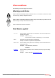
Conventions The following conventions apply in this manual. Warnings and Notes Used to indicate a potentially hazardous situation which, if not avoided, could result in death or serious injury. Example: dangerous tension. Used to indicate a potentially hazardous situation which, if not avoided, may result in minor or moderate injury. Example: electrostatic discharge. i Used for additional information and advice.
Conventions
Table of Contents Conventions Warnings and Notes Font Styles applied 5 5 5 1 Getting started Handling Safety Instructions 11 11 11 2 Installation of the Network Adapter 13 3 Connection of the Network Adapter Transmission Distances Connection to the Network 15 15 15 4 Installation of the Driver Software Windows Windows NT 4.
Table of Contents 6 Testing the Network Adapter Diagnostics Program Loopback Test for Fiber Adapters Repeater Test for Copper Adapters Failure of a Test Additional Functions of the Diagnostics Program Checking Other Displays and Data Main Program Reading Sensor Data Reading Configuration Data Reading VPD Data Sample Usage of VPD Data/Asset Tag 45 45 45 47 48 49 49 49 50 50 51 52 7 Troubleshooting Searching for errors LED Displays 55 55 56 8 Important Information Technical Support Returning an Adapte
Table of Figures Figure 1: Insertion of the adapter into the computer 14 Figure 2: Connection of fiber-optic cables/plugs 16 Figure 3: Adapter Overview in “SysKonnect Network Control” 41 Figure 4: Display after a VCT test 43 Figure 5: Setup for loopback testing 45 Figure 6: Typical screen display after a successful test 46 Figure 7: Typical error message from the diagnostics program 48 Figure 8: Diagnostics program, main menu 49 Figure 9: Display of configuration data 51 Figure 10: VPD Dat
Table of Figures
1 Getting started To install the network adapter, observe the following instructions. Handling Electrostatic discharge! Electrostatic discharge may damage or destroy the network adapter. To avoid damaging the network adapter: • • • • • • • • • • • • Switch off the computer and disconnect the power cord from the power outlet. Do not open the antistatic bag until you are ready to install the network adapter. We recommend to wear an antistatic wrist strap when installing the network adapter.
1 Getting started To avoid damaging your eyes and to continue safe operation in case of abnormal circumstances: • • • Never look directly into the outlets of fiber-optic cables or fiber-optic transmission components with unprotected eyes! Never allow fiber-optic transmission paths to operate until all the connections have been made. Always fit protective plugs to any unused ports on the switch or the network adapter.
2 Installation of the Network Adapter The installation procedure in Hot Plug systems may differ from the following. For Hot Plug systems read the corresponding documentation. Have the computer manual ready and if necessary, a key and/or screwdriver to open the cover and remove the bracket. To install the adapter in the computer, proceed as follows: 1. 2. 3. 4. 5. i Switch off the computer in which the network adapter is to be installed. Disconnect the power cord from the power outlet.
2 Installation of the Network Adapter Figure 1.
3 Connection of the Network Adapter The physical connection of the network adapter to the network is described in this chapter. General instructions for driver installation are given in chapter 4 "Installation of the Driver Software". Transmission Distances Depending on the physical media (cable) different distances can be reached for transmission with the Gigabit Ethernet adapter: Adapter Type Physical Media Maximum Distance 1000Base-SX 1000Base-SX 50.
3 Connection of the Network Adapter Figure 2. Connection of fiber-optic cables/plugs 7. 8. 9. 10. 11. 12. 13. i Switch on the computer and the switch. If no protocol driver has been loaded, go to chapter 4 "Installation of the Driver Software". After driver installation, return to step 8 of this list. If a protocol driver has been loaded, continue with step 8. Check the correct polarity with the green link LED on the network adapter.
4 Installation of the Driver Software The network drivers are located in the appropriate product directory on the enclosed installation CD-ROM. This directory is organized into a number of subdirectories for the various operating systems. The subdirectories contain the driver files and the corresponding readme files. The readme files are available as ASCII text and in HTML format. Any last-minute changes are documented in the “Release Notes” (if applicable) and on the driver site of the SysKonnect web site.
4 Installation of the Driver Software Windows SysKonnect offers drivers for Windows 2000, Windows XP, Windows Me, Windows 98 SE, and Windows NT 4.0. Additionally, a value added package is available for Windows 2000 and Windows XP enabling Virtual LAN (VLAN) and link aggregation support. This package also includes a utility program for easy installation and configuration.
Windows 19 Windows 98 Second Edition SysKonnect offers an NDIS 5.0 32-bit Miniport driver for the SysKonnect SK-98xx family supporting Windows 98 Second Edition (Windows 98 SE). This driver does not support Windows NT 4.0 or below, Windows 2000, and Windows XP. With PCI adapters, due to the plug & play facility of PCI, Windows 98 SE is able to find, identify, and configure an adapter automatically. To install the driver, proceed as follows: 1.
4 Installation of the Driver Software 7. 8. 9. 10. 11. 12. 13. Type the path to the driver, e.g. e:\SK-982x\Windows\WinME, where ”e” is the designation of the CD-ROM drive on your system. Click NEXT. The menu “Windows has found multiple software packages that should work for this device. What would you like to install?” is displayed. If Windows Me has detected the adapter you have installed in your computer, select the check box THE UPDATED SOFTWARE (RECOMMENDED). Click NEXT.
Windows 21 7. 8. 9. 10. 11. 12. 13. 14. 15. 16. 17. 18. 19. 20. 21. 22. i Select the tab DRIVER. Click UPDATE DRIVER.... The window “Upgrade Device Driver Wizard“ is displayed. Click NEXT. In the same window, the menu “Install Hardware Device Drivers” is displayed. Select the check box DISPLAY A LIST OF THE KNOWN DRIVERS FOR THIS DEVICE SO THAT I CAN CHOOSE A SPECIFIC DRIVER. Click NEXT. The menu “Hardware Type“ is displayed. Select NETWORK ADAPTER. Click NEXT.
4 Installation of the Driver Software 8. 9. Update the driver In case the adapter has not passed Windows Logo testing to verify its compatibility with Windows XP, the window “Hardware Installation” is displayed. To continue the installation, click CONTINUE ANYWAY. In the window ”Found New Hardware Wizard”, the menu “Completing the Found New Hardware Wizard” is displayed. Click FINISH to complete the installation. To update the driver, proceed as follows: 1. 2. 3. 4. 5. 6. 7. 8. 9. 10. 11. 12. 13.
Windows 23 SysKonnect Network Driver Windows 2000 and Windows XP Installation Package for The “SysKonnect Network Driver Installation Package” for the SysKonnect SK-98xx family contains the NDIS 5.0 and 5.1 32-bit Miniport drivers, the Virtual LAN (VLAN) intermediate driver, the Link Aggregation (LAGG) intermediate driver, and the utility program “SysKonnect Network Control”. The package supports Windows 2000 and Windows XP. The installation process is identical for Windows 2000 and Windows XP.
4 Installation of the Driver Software Linux The “sk98lin” driver for the SysKonnect SK-98xx family supports all Linux distributions. The installation procedure for the various Linux distributions differs. The driver will be integrated into the kernel, i.e. using the standard installation procedure of your distribution to install Ethernet adapters should cause no problems. For details on the installation of Ethernet adapters, refer to the distribution’s manual.
Linux 25 9. 10. 11. 12. 13. 14. 15. 16. 17. 18. 19. 20. 21. 22. 23. 24. 25. 26. Load the module The Main Menu is displayed. Select LOADABLE MODULE SUPPORT. The menu “Loadable module support“ is displayed. Select ENABLE LOADABLE MODULE SUPPORT. Select KERNEL MODULE LOADER. Select EXIT. Configure other options, e.g. SCSI, file systems, etc. To quit the configuration, select EXIT. When the message “Do you wish to save your new kernel configuration” is displayed, select YES.
4 Installation of the Driver Software 2. i “ethX: network connection up using port Y” and showing the selected connection parameters. Now your adapter should be fully operational. Execute ping to verify the connection to other computers on your network. If you are in doubt about the IP addresses, ask your network administrator for assistance. For more information, refer to the corresponding readme file.
Sun Solaris 27 If you have typed y in step 4, continue with step 6. If you have typed n in step 4, only the driver will be loaded and all interfaces have to be configured manually. For details, refer to the corresponding readme file. 6. Enter the following values for every interface you want to configure as the system requests them: • the new interface's name (e.g. host), • the IP address (e.g. 192.9.121.59), and • the netmask (e.g. 255.255.255.0).
4 Installation of the Driver Software 12. 13. 14. 15. 16. Once you have entered all information, the message “Are these settings OK (y/ n)?” is displayed. If all settings are OK, type y. Press . The message “Do you have more SysKonnect Gigabit Ethernet interface adapters installed (y/n)?” is displayed. If yes, type y. If no, type n. Press . If you have typed y in step 14, repeat steps 11 to 13. If you have typed n, continue with step 16.
IBM AIX 29 9. 10. 11. 12. Select SKGE. Select ACTIONS > INSTALL (ANALYSIS). When the analysis is finished, confirm with OK. Click YES. The following message will be displayed: “The system will be rebooted as soon as Installation is complete. Do you still wish to start Installation?”. 13. Confirm with YES. 14. After the installation is completed, click DONE. 15. Click OK to reboot. The driver has been installed and the network adapter can now be configured.
4 Installation of the Driver Software 4. Copy the driver file .pck to any directory on your AIX 4.3.3 operating system with the following command: cp /.pck /tmp/.pck Automatic installation on AIX 4.3.3, AIX 5.1, and AIX 5.2 The following description of the installation process refers to ”smitty” executed from the console login. The automatic installation on AIX 4.3.3, AIX 5.1, and AIX 5.2 is identical.
Novell NetWare 31 The menu “Install and Update from Latest Available Software” is displayed. 12. Press . The message “Are you sure?” is displayed. 13. Press to start the installation process. 14. Once the installation has been completed, start the configuration manager ”cfgmgr” from the command line by entering cfgmgr. This command executes a search for installed adapters and loads the corresponding drivers. For more information, refer to the corresponding readme file.
4 Installation of the Driver Software Installation on Novell NetWare 4.20 To install the network driver on Novell NetWare 4.20, proceed as follows: 1. 2. 3. 4. 5. 6. 7. 8. 9. 10. 11. 12. 13. 14. 15. 16. After you have installed the adapter in your computer, boot NetWare 4.20 (for details, see chapter 2 "Installation of the Network Adapter"). On the console, execute the following command: load install. Select DRIVER OPTIONS (LOAD/UNLOAD DISK AND NETWORK DRIVERS).
Novell NetWare 33 5. Type the path to the driver. If you are installing from CD-ROM, the menu “Select an action” is displayed. Here, select CONTINUE AND ACCESS THE CD-ROM. The menu “Select a driver to install” is displayed. 6. Select the driver for your network adapter. The message “Do you want to copy driver .LAN?” is displayed. 7. To copy the driver to the server, select YES.
4 Installation of the Driver Software
5 Features The SysKonnect SK-98xx V2.0 Gigabit Ethernet Adapters define a series of network interfaces and constitute a follow-up model of the SK-98xx Gigabit Ethernet Server Adapters. Currently, two versions of SysKonnect SK-98xx V2.0 Gigabit Ethernet Adapters are available. Both versions are single link network interfaces. At the moment, SysKonnect offers one fiber single link version with SC duplex connector and a copper version, which supports 1000BaseT, 100Base-T, and 10Base-T with an RJ-45 connector.
5 Features Operating System Support The drivers for the SysKonnect SK-98xx V2.0 Gigabit Ethernet Adapters support the following operating systems: • • • • • • Windows NT 4.0, Windows 98 Second Edition, Windows Millennium Edition, Windows 2000, and Windows XP Linux kernel 2.2.x and 2.4.x Novell NetWare 4.20 or higher, Novell NetWare 5 and 6 Sun Solaris 7, 8, and 9 on SPARC systems as well as Solaris 7 and 8 on X86 systems IBM AIX 4.3.3, AIX 5.1, and AIX 5.2 HP-UX 11.00 (PA-RISC 32/64-bit), HP-UX 11.
Advanced Power Management / Wake on LAN 37 Advanced Power Management / Wake on LAN The SysKonnect SK-9821 V2.0 Gigabit Ethernet Adapter supports power management as defined in the PCI Bus Power Management Interface Specification V1.1 and Network Device Class Power Management Reference Specification V2.0. The power management features are implemented according to the Advanced Configuration and Power Interface Specification V2.0. The SysKonnect SK-9821 V2.
5 Features Link aggregation provides the following important benefits: • • • Higher link availability Increased link capacity Improvements are obtained using existing hardware (no upgrading to higher-capacity link technology is necessary) Demanding applications running in high-performance environments like servers in enterprises, web servers, and intranet servers gain particularly from the high-bandwidth and duplex capabilities of link aggregation.
User Diagnostics (DOS) 39 The following conditions have to be met in order for Hot Plug to work on SysKonnect Gigabit Ethernet adapters: • • • The target system has PCI Hot Plug slots, i.e. the power can be switched on and off under the control of the operating system. The adapter is installed in one of the PCI Hot Plug slots. The operating system supports PCI Hot Plug on the target system. The drivers for the following operating systems support PCI Hot Plug: • • • Windows 2000, Windows XP NetWare 4.
5 Features The various tabs contain trees showing the currently installed adapters and their configuration: • • • • • • • • • • • The “Adapter” tab displays the network adapters available in your system with their corresponding ports. It shows the ports, which have been configured as VLANs, for RLMT and those, which have been aggregated into a team. This tab only serves as an overview. For configuration of the adapter, select one of the other tabs.
Virtual LAN (VLAN) support 41 When a component in the tree is selected, the corresponding parameters are displayed. Figure 3. Adapter Overview in “SysKonnect Network Control” For more information on the “SysKonnect Network Control”, refer to the online help available for this program (click the HELP button when the program is running). Virtual LAN (VLAN) support A Virtual LAN is a group of network devices that belong to the same network segment, regardless of the physical network structure.
5 Features By means of frame tagging, SysKonnect SK-98xx V2.0 Gigabit Ethernet Adapters can support up to 64 IP address assignments in a single network connection. Thus, multiple VLANs can be configured for one port. Stations can be accessed from systems in multiple IP sub nets without traversing routers. Additionally, multiple application VLANs can be defined to isolate traffic for performance and security purposes.
Virtual Cable Tester™ (VCT) 43 Figure 4. Display after a VCT test SysKonnect SK-98xx V2.
5 Features
6 Testing the Network Adapter Diagnostics Program The network adapter can be tested with the supplied diagnostics program (running on DOS). The diagnostics program runs offline, i.e. normal operation of the network adapter can not be maintained. During testing the link of the tested port will be down, i.e. no data can be transferred.
6 Testing the Network Adapter To test the adapter, proceed as follows: 1. 2. 3. 4. 5. 6. 7. 8. 9. Switch off the computer. If the computer is still connected to the data network, unplug the data cable from the network adapter’s port. Connect the network adapter as follows: • For the simple test: Insert the protective plugs into the ports. • For the loopback test: Insert the loopback connector into the port. Boot to DOS. Wait until the operating system is loaded and the DOS prompt is displayed.
Diagnostics Program 47 . If the adapter is not connected immediately to the data network, insert the protective plug for safety reasons (otherwise laser light may be emitted) and as a protection against dust and dirt. Repeater Test for Copper Adapters For the SK-982x adapter series the test via wrap plug is not available.
6 Testing the Network Adapter Failure of a Test Figure 7. Typical error message from the diagnostics program For a test to be completed successfully, each of the following conditions must be met: • • • The network adapter operates correctly. The network adapter is cabled correctly for the test or is equipped with the correct connectors. The network adapter has been installed correctly in the computer. The message failed does not necessarily imply that the network adapter is faulty.
Additional Functions of the Diagnostics Program 49 Additional Functions of the Diagnostics Program Checking Other Displays and Data In addition to performing the three network adapter tests, the diagnostics program can also read out network adapter-specific data that may be useful for pinpointing the causes of failure. You can • • • • read sensor data, read configuration data, read and write VPD data, read and write Flash EPROM data. Main Program To start the main program, proceed as follows: 1. 2. 3.
6 Testing the Network Adapter Reading Sensor Data To read sensor data, proceed as follows: 1. 2. 3. Start the main program (see page 49). Select SHOW SENSORS in the main menu. A separate window will be displayed for the following sensor data: • Temperature of the board • Voltage on the PCI card • Voltage on the PCI I/O lines • Other supply voltages In the main menu, SHOW SENSORS changes to HIDE SENSORS. You can close the window by selecting HIDE SENSORS in the main menu.
Additional Functions of the Diagnostics Program 51 Figure 9. Display of configuration data Reading VPD Data To read VPD data (Vital Product Data), proceed as follows: 1. 2. Start the main program (see page 49). Select VPD DATA in the main menu. A submenu with the following options will be displayed: • EXIT (return to the main menu) • DISPLAY VPD DATA • CLEAR ERROR LOGS • ADD/MODIFY VPD DATA (you can enter user-defined data and keywords here) • DELETE VPD KEYWORDS Figure 10.
6 Testing the Network Adapter 3. Select the desired option or Return to the main menu by selecting EXIT (default option). Sample Usage of VPD Data/Asset Tag Example You want to store the inventory number of the network interface adapter (123-45) in the asset tag. To store the inventory number, proceed as follows: 1. 2. 3. Look at all the VPD data to determine the code for the asset tag. Start the main program (see page 49). Select VPD DATA > DISPLAY VPD DATA.
Additional Functions of the Diagnostics Program 53 After modifying the asset tag your screen should display the following: Figure 12. Screen showing updated asset tag For more information on the diagnostics program, refer to the readme file. To open the readme file, proceed as follows: 1. 2. 3. 4. 5. 6. Insert the installation CD-ROM into your CD-ROM drive. On the start page of the CD-ROM, click DRIVERS. Select GIGABIT ETHERNET. Select SK-98XX GIGABIT ETHERNET ADAPTERS.
6 Testing the Network Adapter
7 Troubleshooting Searching for errors Problem What to do Another expansion card fails to work after the network adapter has been installed Make sure all cables are connected to the correct expansion cards. Make sure the expansion cards are correctly inserted and check if any internal connections in the computer have been disengaged or were damaged during the installation of the network adapter. Check for resource conflicts in the computer. Check PCI configuration and resource allocation.
7 Troubleshooting LED Displays Once the driver has been installed, the adapter is operational. The current status is indicated by the LEDs. Copper adapter Fiber adapter Figure 13.
8 Important Information Technical Support If you encounter any problems, read the relevant sections of the manual and the readme files on the CD-ROM. If you cannot solve your problems, consult our technical support.
8 Important Information 3. 4. 5. i Return the form to us. We will send you a unique reference number and inform you if the product is still under warranty. Send us the faulty product packed in an antistatic bag, with a copy of the completed form enclosed in its original packaging (or comparable packaging). Write the reference number issued by SysKonnect clearly visible on the outer packaging. SysKonnect cannot accept any returned product without an RMA number on the outer packaging.
Technical Specifications 59 Technical Specifications Network interface standard IEEE 802.3z, IEEE 802.3ab, IEEE 802.3x, IEEE 802.1p, IEEE 802.1q, IEEE 802.3, IEEE 802.3u, IEEE 802.3ac, IEEE 802.
8 Important Information
Appendix A. License and Warranty Information The Americas, Asia, Australia, New Zealand, Pacific Dear Customer, if you acquired your SysKonnect product in the UNITED STATES, CANADA or any other country in the AMERICAS, ASIA, AUSTRALIA, NEW ZEALAND, PACIFIC, the following license and purchase agreement applies to you. This is a legal agreement between you, the end user and SysKonnect Incorporation, a California U.S.A. Incorporation (SysKonnect Inc.). SysKonnect Inc.
Appendix A. License and Warranty Information No other Warranties SysKonnect Inc. disclaims all other warranties or liabilities with respect to the SOFTWARE, the HARDWARE, the accompanying Product Manual(s) and other written materials and any other accessories. No Liability for Consequential Damages SysKonnect Inc. does not warrant the software and hardware for a specific application, nor does SysKonnect Inc. accept any consequential damages due to the use of the hardware or software. SysKonnect Inc.
Deutschland, Schweiz, Österreich, Liechtenstein 63 SysKonnect warrants that NETWORK INTERFACE CARDS will be free from defects in materials and workmanship under normal use and service for a period of 5 years from the date of receipt, that NETWORK INFRASTRUCTURE COMPONENTS (e.g.
Appendix A. License and Warranty Information Sie dürfen weder die Handbücher des Produktes noch anderes schriftliches Begleitmaterial zur Software oder Hardware kopieren.
Appendix B. Compliance Statements FCC Declaration of Conformity Compliance Information Statement - Class B NOTE: This equipment has been tested and found to comply with the limits for a “Class B” digital device, pursuant to Part 15 of the FCC rules. These limits are designed to provide reasonable protection against harmful interference in a residential installation.
Headquarters Americas, Canada, and Pacific Rim Europe, Middle East, and Africa SysKonnect GmbH A Marvell®Company Siemensstrasse 23 D-76275 Ettlingen SysKonnect, Inc. A Marvell®Company 700 First Avenue Sunnyvale, CA 94089 SysKonnect Ltd. A Marvell®Company 55 Henley Drive Frimley Green, Camberley Surrey, Gu16 6NF Germany USA United Kingdom Sales: + 1 800 716 3334 + 1 408 222 0809 Support: + 1 866 782 2507 + 1 408 222 0666 Fax: + 1 408 752 9040 Phone: Fax: E-mail: info@syskonnect.