
Data Sheet


RM9000
Multiprotocol 2.4GHz Wireless Module
Datasheet
13 / 17
System Design Co., Ltd.
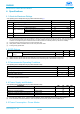
Co-channel rejection
(1)
Wanted signal at –67 dBm, modulated interferer in
channel,BER = 10
–3
–7
dB
Selectivity, ±2 MHz
(1)
Wanted signal at –67 dBm, modulated interferer at
±2 MHz, Image frequency is at –2 MHz, BER =
10
–3
8 / 4
(2)
dB
Selectivity, ±4 MHz
(1)
Wanted signal at –67 dBm, modulated interferer at
±4 MHz, BER = 10
–3
36 / 36
(2)
dB
Selectivity, ±6 MHz
(1)
Wanted signal at –67 dBm, modulated interferer at
±6 MHz, BER = 10
–3
37 / 36
(2)
dB
Selectivity, image frequency
(1)
Wanted signal at –67 dBm, modulated interferer at
image frequency, BER = 10
–3
4
dB
Selectivity, image frequency
±2 MHz
(1)
Note that Image frequency + 2 MHz is the Co-
channel. Wanted signal at –67 dBm, modulated
interferer at ±2 MHz from image frequency, BER =
10
–3
–7 / 36
(2)
dB
Out-of-band blocking
(3)
30 MHz to 2000 MHz
–16
dBm
Out-of-band blocking
2003 MHz to 2399 MHz
–21
dBm
Out-of-band blocking
2484 MHz to 2997 MHz
–15
dBm
Out-of-band blocking
3000 MHz to 12.75 GHz
–12
dBm
Intermodulation
Wanted signal at 2402 MHz, –64 dBm. Two
interferers at 2408 and 2414 MHz respectively, at
the given power level
–38
dBm
(1) Numbers given as I/C dB
(2) X / Y, where X is +N MHz and Y is –N MHz
(3) Excluding one exception at F
wanted
/ 2, per Bluetooth Specification
(4) Suitable for systems targeting compliance with worldwide radio-frequency regulations ETSI EN 300 328 and EN 300 440 Class 2
(Europe), FCC CFR47 Part 15 (US), and ARIB STD-T66 (Japan)
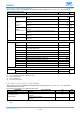
4.11
Bluetooth Low Energy - Transmit (TX)
Measured on the CC1352PEM-XD7793-XD24-PA24 reference design with T
c
= 25 °C, V
DDS
= 3.0 V, f
RF
= 2440 MHz with
DC/DC enabled and high power PA connected to V
DDS
unless otherwise noted.
All measurements are performed at the antenna input with a combined RX and TX path, except for high power PA which is
measured at a dedicated antenna connection. All measurements are performed conducted.
PARAMETER
TEST CONDITIONS
MIN TYP MAX
UNIT
General Parameters
Max output power,
high power PA
Differential mode, delivered to a single-ended 50 Ω load through a balun
19.5
dBm
Output power
programmable
range
high power PA
Differential mode, delivered to a single-ended 50 Ω load through a balun
6
dB
Max output power,
high power PA, 10
dBm configuration
(4)
Differential mode, delivered to a single-ended 50 Ω load through a balun
10.5
dBm
Output power
programmable
range
high power PA, 10
dBm configuration
(4)
Differential mode, delivered to a single-ended 50 Ω load through a balun
5
dB
Max output power,
regular PA
Differential mode, delivered to a single-ended 50 Ω load through a balun
5
dBm
Output power
programmable
range,
regular PA
Differential mode, delivered to a single-ended 50 Ω load through a balun
26
dB
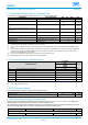
Measured on the CC1352PEM-XD7793-XD24-PA24 reference design with T
c
= 25 °C, V
DDS
= 3.0 V, f
RF
= 2440 MHz with
DC/DC enabled and high power PA connected to V
DDS
unless otherwise noted.
All measurements are performed at the antenna input with a combined RX and TX path, except for high power PA which is