
Manual

SS-450-000 4 I56-3387-006R
©2013 System Sensor
System Sensor warrants its enclosed smoke detector base to be free from defects in mate-
rials and workmanship under normal use and service for a period of three years from date
of manufacture. System Sensor makes no other express warranty for this smoke detector
base. No agent, representative, dealer, or employee of the Company has the authority to
increase or alter the obligations or limitations of this Warranty. The Company’s obligation
of this Warranty shall be limited to the repair or replacement of any part of the smoke
detector base which is found to be defective in materials or workmanship under normal
use and service during the three year period commencing with the date of manufacture.
After phoning System Sensor’s toll free number 800-SENSOR2 (736-7672) for a Return
Authorization number, send defective units postage prepaid to: System Sensor, Returns
THREE-YEAR LIMITED WARRANTY
Department, RA #__________, 3825 Ohio Avenue, St. Charles, IL 60174. Please include a
note describing the malfunction and suspected cause of failure. The Company shall not
be obligated to repair or replace units which are found to be defective because of damage,
unreasonable use, modifications, or alterations occurring after the date of manufacture.
In no case shall the Company be liable for any consequential or incidental damages for
breach of this or any other Warranty, expressed or implied whatsoever, even if the loss
or damage is caused by the Company’s negligence or fault. Some states do not allow the
exclusion or limitation of incidental or consequential damages, so the above limitation
or exclusion may not apply to you. This Warranty gives you specific legal rights, and you
may also have other rights which vary from state to state.
Please refer to insert for the Limitations of Fire Alarm Systems
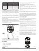
PLASTIC LEVER
BREAK TAB AT
DOTTED LINE BY
TWISTING TOWARD
CENTER OF BASE.
USE SMALL-BLADED
SCREWDRIVER TO
PUSH PLASTIC LEVER
IN DIRECTION OF
ARROW.
SLOT
C0144-00
C1082-00
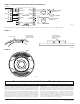
FIGURE 7A:
FIGURE 7B:
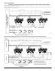
FIGURE 6: SYNCHRONIZATION DIAGRAM (FOR MDL SERIES SYNC MODULES ONLY)
C1090-00
NOTE: Wiring shown for System Sensor MDL Series Sync Module. For additional wiring configurations, see your sync module manual.
FACP #1
+
–
+
–
+
–
+
–
+
–
+
–
+
–
EOL
(1)
}
}
}
}
HORN
CONTROL
ZONE 1
IN
ZONE 2
IN
SLAVE
IN
+
–
+
–
+
–
+
–
}
}
}
}
ZONE 1
OUT
ZONE 2
OUT
NAC
SLAVE IN
SLAVE
OUT
TEMP JUMP OFF
NAC 1
}
B+
B–
NAC 2
}
B+
B–
NAC 3
}
B+
B–
TO NEXT DEVICE
OR EOL (1)
TO NEXT DEVICE
OR EOL (1)
2 STYLE Y ZONES
(CLASS B)
MASTER
SOUNDER
BASE
SOUNDER
BASE
OPTIONAL