
Owner's manual
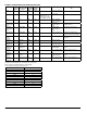

Sensitivity
Setting
Percent
Obscuration
Display
Reading
Acceptable Distance
Between Detector & Reflector
Feet Meters
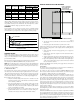
Level 1 25 25 16.4 to 120 5.0 to 36.6
Level 2 30 30 25 to 150 7.6 to 45.7
Level 3 40 40 60 to 220 18.3 to 67
Level 4 50 50 80 to 328 24.4 to 100
Acclimate
Level 1
30 to 50 A1 80 to 150 24.4 to 45.7
Acclimate
Level 2
40 to 50 A2 80 to 220 24.4 to 67
In addition to the four standard sensitivity selections the detector has two Ac-
climate settings. When either of these settings is chosen the detector will au-
tomatically adjust its sensitivity using advanced software algorithms to select
the optimum sensitivity for the environment. The sensitivity will be continu-
ously adjusted within the ranges specified in the chart above.
SENSITIVITY
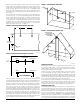
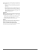
Total obscuration can be converted to percent per foot, assuming uniform
smoke density for the entire length of the beam. The charts below converts
total obscuration to percent per foot for all acceptable sensitivity settings.
2.0
1.5
1.0
0.5
0.0
0
25% SETTING
30% SETTING
40% SETTING
50% SETTING
50 100 150 200 250 300 350
OBSCURATION (%/FT.)
SENSITIVITY IN PERCENT PER FOOT VS. DISTANCE
(ASSUMES UNIFORM SMOKE DISTRIBUTION)
DISTANCE IN FEET
C0268-00
SENSITIVITY TESTING
NOTE: Before testing, notify the proper authorities that the smoke detector
system is undergoing maintenance, and therefore the system will be tempo-
rarily out of service. Disable the zone or system undergoing maintenance to
prevent unwanted alarms.
Detectors must be tested after installation and following periodic maintenance.
The sensitivity of the BEAM200/BEAM200S may be tested as follows:
NOTE: Before testing the detector, check for the presence of the flashing green
LED at the receiver, making sure not to disturb or block the beam. If it does
not flash and the detector is not in trouble or alarm, power has been lost to
the detector (check the wiring).
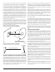
A. Calibrated Test Filter
The sensitivity of the detector can be tested using an opaque material to cover
the reflector by an amount indicated by the graduated scale on the reflector.
(Due to the high optical efficiency of the reflector the selection of the opaque
material used to block the reflector is not critical. Acceptable materials in-
clude, but aren’t limited to, this manual or the cardboard packaging inserts.)
Refer to Figure 14 for this procedure.
1. Verify the sensitivity setting of the detector in % obscuration. See the
Sensitivity Selection section of this manual for sensitivity determina-
tion if sensitivity is unknown.
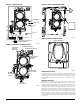
2. Place the blocking material over the reflector, lining it up with the
graduated marks that are 10 less than the detector’s setting in % ob-
scuration. The detector should not alarm or fault. Keep the material
in place for a minimum of 1 minute.
3. Place the blocking material over the reflector lining it up with the
graduated marks that are 10 more than the detectors setting in %
obscuration. The detector should enter alarm within 1 minute.
FIGURE 14. REFLECTOR TEST CARD PROCEDURE
LINE UP EDGE OF
TEST CARD WITH
APPROPRIATE
OBSCURATION LEVEL
MOVE TEST CARD TO DESIRED AMOUNT OF OBSCURATION
C0267-00
4. The detector can be reset with the reset switch on the detector unit or
remote reset.
5. Notify the proper authorities that the system is back on line.
If the detector fails this test several steps should be taken to determine if the
detector is faulty or simply needs to be re-adjusted before returning the unit.
These steps include:
1. Verify all wiring connections and appropriate power is applied to
the detector.
2. Verify that the optical line of sight is free from obstructions and re-
flective objects.
3. Apply the maintenance procedure in this manual. Repeat the test pro-
cedure. If the detector still fails the test procedure proceed with step 4.
4. Repeat the alignment procedure in this manual. If the alignment pro-
cedure is successful repeat the test procedure. If the detector still fails
the test it should be returned.
NOTE: For the BEAM200S the external power supply must be connected for
the test switch to work.
B. Test Switch
The detector can be tested using the local test switch on the transmitter/re-
ceiver unit or remotely using the remote test station.
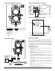
The remote test station can be used with the BEAM200/BEAM200S beam
smoke detector. Follow instructions included with the test station for proper
use. See Figure 8 (Remote Test Station) for wiring diagram.
The BEAM200S is equipped with an integral sensitivity test feature that con-
sists of a calibrated test filter attached to a servo motor inside the detector
optics. When a test is initiated using the remote test station or local test switch
the test filter is moved in the pathway of the light beam. The on-board micro-
processor then determines if the proper level of signal reduction is received
at the receiver. If the proper level of signal reduction is received the detector
will enter alarm. If the proper level of signal reduction was not achieved, indi-
cating that the sensitivity of the detector is out of tolerance, the detector will
enter the trouble condition.
Always perform a complete reflector blockage test as in step 4 of the Instal-
lation/Alignment procedure to Ensure that the pathway between the detector
and reflector is clear.
NOTE: For the BEAM200 this test does not satisfy the requirements of NFPA72
for periodic maintenance and sensitivity verification of beam type detectors.
For the BEAM200S this test in conjunction with the complete reflector block-
age test (see step 4 of the Installation/Alignment procedure in this manual)
does satisfy the requirements of NFPA72 for periodic maintenance and sensi-
tivity verification of beam type detectors.
D400-74-00 8 I56-2289-005R