
Smoke Alarm User Manual


4
Note: This document is based on the recommendations of BS5839 Part 1: 2002. It is intended only as a guide to the application of fire detection systems.
Reference must be made to relevant national and local standards.
1. INTELLIGENT FIRE ALARM
SYSTEMS
1.1. INTRODUCTION
Conventional fire alarm systems provide an adequate and
cost effective fire alarm system for many small buildings. In
larger, more complex buildings however, more sophisticated
‘intelligent’ fire alarm systems tend to be used. These
systems offer benefits in speed of detection, identification
of the location of a fire and easier maintenance. Intelligent
systems also offer tolerance to faults in the system wiring,
which allows a single pair of wires to be used to connect up
to 198 devices to the system, allowing cost savings in the
wiring of large systems. In larger installations, the benefits
of improved maintenance and reduced cabling cost are
overwhelming. Currently, the point at which an intelligent
system becomes economical is around 6 zones in the UK.
This guide is intended as an introduction to the technology
used in intelligent fire alarm systems. For more information
on conventional systems, refer to System Sensor’s ‘Guide to
Conventional Fire Systems’.
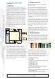
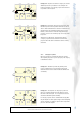
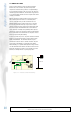
Figure 1.1.1 Intelligent Fire Alarm Systems
Figure 1.1.1 demonstrates an example of a single loop
intelligent fire system layout. The wiring is looped, and
connects to the control panel at each end. All detectors, call
points, sounders and interface modules are wired directly
to the loop, each having its own address. The control panel
communicates with each device on the loop, and if an alarm or
fault condition is signalled, or if communications are lost with
one or more detectors, the appropriate response is triggered.
The loop can be powered from each end so that if the loop is
broken at any point, no devices are lost. In addition the use of
short circuit isolators minimises the area of coverage lost in
the case of a short circuit.
INTELLIGENT
FIRE ALARM
CONTR
OL
PANEL
EOL
EOL
ISOLATOR
CONTROL
MODULE
MONITOR
MODULE
ISOLATO
R
ISOLATO
R
CONVENTIONAL
ALARM ZONE
CONTAC
T
(E.G. SPRINKLER
SWITCH
FIRE ALARM SYSTEM OK
28
January 2004
14:01
SYSTEM OK
SYSTEM RESET
FIRE ALARM
FAUL
T
1.2. INTELLIGENT SYSTEM TYPES
There are two methods commonly used for implementing
intelligent fire systems:
The most common type of system is “Analogue”. In this
case the detector (or sensor) returns a value to the panel
representing the current state of its sensing element(s). The
control panel compares this value with the alarm threshold
in order to make the decision as to whether a fire is present.
Note that the term analogue, used to describe these systems
does not refer to the communication method (indeed many
“analogue” fire systems use digital communications) but to
the variable nature of the response from the detector to the
control panel.
In “Addressable” type intelligent systems, mainly used to meet
the requirements of the French market, detector sensitivity is
programmed to each device by the control panel or is preset
in the factory. The detector compares its current sensor value
with the configured threshold to make the alarm decision,
which is then transmitted to the panel when the sensor is
interrogated.
In many systems the features offered by the two detection
techniques are so similar that it is not particularly relevant
which technique is used to make the alarm decision. It is
better to select a system based on the features offered by the
system as a whole.
1.3. COMMUNICATION PROTOCOL
Intelligent systems use the same pair of wires both to supply
power to the loop, and to communicate with devices on the
loop. The communication language, or protocol used varies
from manufacturer to manufacturer, but generally comprises
switching of the 24V supply voltage to other voltage levels to
achieve communication.
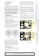
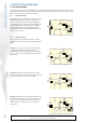
Figure 1.3.1 Typical Protocol Configuration
A typical basic protocol comprises two main parts (See
Fig 1.3.1): A query or poll of a device by the control panel
including the device address and control information, and
a response from the device giving its status and other
information. Precise details of the information transferred will
depend on the manufacturer, but normally will include:
Poll: Control Panel to device:
• Device address
• Control of device LED - blink to indicate polling, switch
on when device is in alarm
• Control of device self-test
• Control of module output
• Error detection for example parity bit or checksum
Response: Device to Control Panel
• Device type (e.g. optical detector, heat detector, multi-
sensor detector, module)
• Analogue Signal - i.e. the current sensor value
Intelligent Fire Alarm Systems
Panel to detector
Detector Response
Control
Error Chec
k
Detector
Address
Device
Type
Test Status
Sensor
Value
Other Info
e.g. drift
status
+24V