
Smoke Alarm User Manual

5
Note: This document is based on the recommendations of BS5839 Part 1: 2002. It is intended only as a guide to the application of fire detection systems.
Reference must be made to relevant national and local standards.
• Alarm Signal if appropriate
• Status of module output
• Remote test status
• Manufacturer code
Most commonly, each device on the loop will be polled in turn,
however to increase speed around a loop, some protocols
allow polling of groups of devices on a single communication.
Note that since different manufacturers have their own
protocols, it is important to ensure compatibility between
the detectors and control panel you intend to use. Some
detector manufacturers produce intelligent detectors
with different communication protocols for different
customers, so two detectors which look virtually
identical in appearance may not be compatible. Always
check with the manufacturer of the control panel.
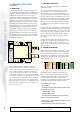
1.4. ADDRESSING METHODS
Different manufacturers of intelligent systems use a number
of different methods of setting the address of a device,
including:
• 7-bit binary or hexadecimal DIL switch
• Dedicated address programmer
• Automatic, according to physical position on the loop
• Binary ‘address card’ fitted in the detector base
• Decimal address switches
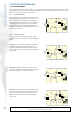
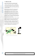
System Sensor’s Series 200 plus range of intelligent devices
uses decimal address switches to define a device’s address
between 00 and 99 (See Figure 1.4.1). This is a simple
intuitive method, not requiring knowledge of binary or
purchase of specialised equipment to set addresses.
Figure 1.4.1 System Sensor decade address switches
-Address 03 selected
Differences in the protocol between detectors and modules
allow them to have the same address without interfering
with each other, and normally address 00 (the factory default
setting) is not used within a system so that the panel can
identify if a device address has not been set: Hence a total of
up to 198 devices - 99 detectors and 99 modules (including
call points, sounders, input and output modules) may be
connected to a loop.
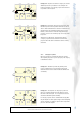
1.5. SYSTEM FAULT TOLERANCE
Due to the looped wiring method used for analogue systems,
they are more tolerant to open and short circuit wiring faults
than conventional systems.
Under normal conditions, the loop will typically be driven
Intelligent Fire Alarm Systems
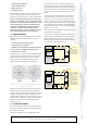
only from one end. If the loop is broken (See figure 1.5.1.),
the panel will detect the loss of communications with the
detectors beyond the break, signal a fault, and switch to drive
the loop from both ends. The system therefore remains fully
operational, and can possibly even indicate the area of the
break.
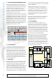
In order to give tolerance against short circuits on the loop,
short circuit isolators are placed at intervals on the loop.
Should a short circuit occur on the loop (Figure 1.5.2.) the
isolators directly on either side of the fault will isolate that
section. The panel will detect the loss of the devices, signal
a fault and drive the loop from both ends, thereby enabling
the remainder of the loop to operate correctly and ensuring
minimum loss of coverage.
Short circuit isolators are available as separate modules and
incorporated into a detector base.
Some products, for example System Sensor’s M200 Series
modules, have isolators built into each of the loop devices.
With this configuration, since only the section of wiring
between the two adjacent devices is isolated there will be no
loss of coverage should a short circuit occur.
Figure 1.5.1. Open Circuit Fault
Figure 1.5.2. Short Circuit Fault
1
1
2
TENS
UNITS
2
3
3
4
4
5
5
6
6
7
7
8
8
0
0
9
9
INTELLIGENT
FIRE ALARM
CONTROL PANEL
24V
24
V
Panel detects the loss of
devices after the break,
signals a fault and powers
from both ends of the loop
to retain full coverage
.
Line break
SYSTEM FAULT: OPEN CIRCUIT:
Zone 2 Module 01
FIRST FLOOR CANTEEN
SYSTEM OK
SYSTEM RESET
FIRE ALARM
FAULT
Isolating
Impedance
Isolating
Impedance
Short Circuit
Isolators on either side of
the short circuit switch an
impedance onto the line
to isolate it.
Devices between the tw
o
isolators are lost,
howe
ver the remainder of
the circuit still operates
correctly
.
Isolators automatically
reset the line when the
short circuit is removed
INTELLIGENT
FIRE ALARM
CONTROL
PANEL
24V
24V
SYSTEM FAULT: SHORT CIRCUIT:
Zone 2 DETECTOR 03
FIRS
T FLOOR CANTEEN
SYSTEM OK
SYSTEM RESET
FIRE ALARM
FAULT