
Home Security System User Manual

INSTALLATION AND MAINTENANCE INSTRUCTIONS
Selectable Output Strobes, Horns, and Horn/Strobes
3825 Ohio Avenue, St. Charles, Illinois 60174
800/736-7672, FAX: 630/377-6495
www.systemsensor.com
D690-03-00 1 I56-2769-003R
For use with the following models: P2R, P2RH, P2RK, P2RHK, P2W, P2WH, P4R, P4RH, P4RK, P4RHK, P4W, P4WH, SR, SRH, SRK, SRHK, SW, SWH, PC2R, PC2RH,
PC2RK, PC2RHK, PC2W, PC2WH, PC4R, PC4RH, PC4RK, PC4RHK, PC4W, PC4WH, SCR, SCRH, SCRK, SCRHK, SCW, SCWH, HR, HRK, HW, SR-P, SW-P, SRH-P, SWH-P,
P2R-P, P2W-P, P2RH-P, P2WH-P, SCR-P, SCW-P, SCRH-P, SCWH-P, PC2R-P, PC2W-P, PC2RH-P, PC2WH-P, P4R-P, P4RH-P, P4W-P, P4WH-P, SR-SP, SRH-SP, P2R-SP, P2RH-SP,
SCW-SP, SCWH-SP, PC2W-SP, PC2WH-SP
Specifications
General Specifications
Standard Operating Temperature: 32°F to 120°F (0°C to 49°C)
K Series Operating Temperature: –40°F to 151°F (FM approved to –31°F); See note for Table 2.
Humidity Range: 10 to 93% non-condensing (indoor products)
Strobe Flash Rate: 1 flash per second
Nominal Voltage: Regulated 12DC/FWR or regulated 24DC/FWR
1
Operating Voltage Range: 8 to 17.5 V (12V nominal) or 16 to 33 V (24 nominal)
Operating Voltage with MDL: 9 to 17.5 V (12V nominal) or 17 to 33 V (24 V nominal)
1
P, S, PC, & SC products will operate at 12 V nominal only for 15 & 15/75 cd.
Mechanical Specifications
Input terminal wire gauge: 12 to 18 AWG
Ceiling mount dimensions (including lens): 6.8˝ diameter×2.5˝ high (173 mm diameter×64 mm high)
Wall mount dimensions (including lens): 5.6˝L×4.7˝W×2.5˝D (142 mm L×119 mm W×64 mm D)
Horn dimensions: 5.6˝L×4.7˝W×1.3˝D (142 mm L×119 mm W×33 mm D)
The products in this manual may be covered by one or more of the following patents:
5,914,665; 5,850,178; 5,598,139; 6,049,446; 6,522,261; 6,661,337; 6,822,400; 6,833,783; 6,856,241.
General Description
The SpectrAlert Advance series of notification appliances
offers a comprehensive range of red and white wall, ceiling,
and outdoor products including horns, strobes, and horn/
strobes. These products are electrically backward compat-
ible with the previous generation of notification appliances.
While there are products specifically designed for use on
the ceiling or the wall, the products are listed to be used
in either application, i.e., wall products could be used on
the ceiling. SpectrAlert products are designed to be used
in either 12 or 24 volt DC or full wave rectified (FWR) sys-
tems. If required, the MDL module may be used in order to
provide synchronization.
NOTICE: This manual shall be left with the owner/user of
this equipment.
Fire Alarm System Considerations
The National Fire Alarm Code, NFPA 72, requires that all
horns, used for building evacuation installed after July 1,
1996, produce temporal coded signals. Signals other than
those used for evacuation purposes do not have to produce
the temporal coded signal.
Power Supply Considerations
Panels typically supply DC filtered voltage or FWR (full
wave rectified) voltage. The system design engineer must
calculate the number of units used on a loop based on the
type of panel supply. Be certain the sum of all the device
currents does not exceed the current capability of the panel.
Calculations are based on using the device current found
in the subsequent charts and must be compatible with the
current specified for the panel or power supply used.
Wire Sizes
The designer must be sure that the last device on the circuit
has sufficient voltage to operate the device within its rated
voltage. When calculating the voltage available to the last
device, it is necessary to consider the voltage drop due to
the resistance of the wire. The thicker the wire, the smaller
the voltage drop. Generally, for purposes of determining the
wire size necessary for the system, it is best to consider all
of the devices as “lumped” on the end of the supply circuit
to simulate worst case. For the most accurate voltage drop
calculations use the System Sensor voltage drop calculator
available on the web or CD-ROM.
Approximate wire resistance:
18 AWG solid: 8 ohms/1000 ft.
16 AWG solid: 5 ohms/1000 ft.
14 AWG solid: 3 ohms/1000 ft.
12 AWG solid: 2 ohms/1000 ft.
NOTE: If Class A wiring is installed, the wire length may be
up to twice as long as on non-fault tolerant circuits.
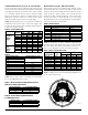
NOTE: For 24 volt applications, the total number of strobes
on a single NAC must not exceed 40, with a maximum loop
resistance of 120 ohms. For 12 volt applications, the total
number of strobes must not exceed 12, with a maximum
loop resistance of 30 ohms.
I56-2769-003R