
MANUAL PSA01
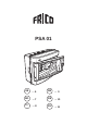


PSA 01
9
Automatic damper- and temperature regulator
Function:
Fan speed and heat output are set on the
PP15 regulator. When the automatic damper-
and temperature regulator PSA01 is used,
the desired room temperature is set on the
thermostat 4 which is located inside the
PSA01 (the internal thermosat of the
fanheater is not in use).
The digital time switch 3 is programmable
on a weekly basis. When the time switch is
in ON-position, day program is active and in
OFF-position the night program is active. For
programming of the time switch, see
separate instructions.
Day program:
The mixing cabinet is open and the day-
temperature is regulated by thermostat 4.
The desired day temperature is set on the
thermostat with the knob marked ”TEMP”.
The desired airmix is set on the positioner 6
for the damper motor.
The setting range is 0-100%.
The rotation of the damper motor can be
switched, see instruction placed inside the
lid of the positioner.
The angle of rotation can be limited (min/
max, see separate instructions for the
positioner).
If there is need during daytime to open the
damper, the positioner is to be set on 0%.
The damper can also be operated manually
by pushing the release button on the motor.
As long as the button is pressed the
damper can be operated manually.
An exhaust fan can be connected to the
regulator by terminals 11 and 12.
The mixing damper can also be regulated
by an exhaust fan or an outdoor thermostat
and will be connected by terminals 13 and
14. If the outdoor thermostat regulates the
damper, the damper will close when the
outdoor temperature drops below the value
set on the thermostat 4 .
When an exhaust fan is used, the damper
will open when the fan starts.
Night program:
The damper is closed and the night
temperature is regulated by the thermostat
4. During the night the desired day
temperature will automatically be reduced
by 0,5 - 10 °C.
For a larger temperature reduction, the
internal thermostat of the fan heater can be
used (wiring diagram is obtainable from
Frico).
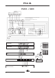
Digital time switch 3
For programming, see separate operating
instructions.
Technical data:
Type: STT-127N
Connection voltage: 230V 50Hz
Max current breakpoint: 10A, 230V AC1
Thermostat 4
The desired day temperature is set on the
thermostat with the knob marked ”TEMP”.
The desired hysteresis is set on the
thermostat with the knob marked ”DIFF” and
is defined as the difference between
connection and disconnection. For optimal
regulation, set the ”DIFF” knob at 0,5.
The desired temperature reduction is set
on the thermostat with the knob marked
”SETBACK”.
The room temperature sensor 5 is
preconnected and located in the gland at
the bottom, to the right in the housing.
N.B! The room sensor must extend about
20mm from the cable gland, which must be
adjusted to obtain correct regulation.
Technical data:
Type: TM1N/D
Connection voltage: 230V +/-15%,
50-60Hz
Max current breakpoint: 10A 230V AC1
Temp setting: -15 – +30 °C
DIFF : 0,5 – 10K
SETBACK: 0 – 10K
Temp sensor: TG-B130
NTC 0-30 °C
GB