
Manual CAR15


CAR 15
5
GB
Operation:
CAR15 adapts the fan speed according to
the temperaure difference between two
temperature sensors. The room sensor is
placed in a representative location in the
occupied zone, approx. 0,5 m above the floor
level. The ceiling sensor is placed on to the
ceiling, preferably higher than the fans, but
not directly above.
Up to 15 pcs of ceiling fans (Frico ICF) can be
connected to the CAR15 .
Regulation:
General description:
The regulator shall be well ventilated (at least
50cm free space around the unit). CAR15
can during operation make a buzzing sound,
placement of the control should be chosen
with consideration to this.
Settings:
The knob ”AUTOMATIC” is used to set
the range of max. temp. difference. If the
"AUTOMATIC" knob is set to 15°C it means
that if the temperature difference between
the sensors is 15°C the fans will run on MAX-
speed and with a difference of 0°C the fans
will run on MIN-speed.
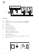
The knob "AUTOMATIC" is in use if the right
switch is set in "AUTOMATIC" position and if
no closing contact is connected to terminals 7
and 8. If there is a closing contact connected
to terminals 7 and 8, the terminals 5 and 6
can be in use for an external 0-10VDC signal.
Note! this is only possible if the right switch is
set in "AUTOMATIC" position.
The knob "MANUEL" is used for overrunning
the temperature sensors and to manually
adjust the fan speed. "MANUEL" is in use if
the right switch is set in "MANUEL" position
For adjustement of the min- or max fan
speed, use the potentiometers "MIN" or "MAX"
(use a small screwdriver). This setting is valid
for all options.
Note! The fans shall always be rotating, even
if only slowly to avoid overheating of the
motor.
The fans can run both forward, pushing
the cushion of warm air from the ceiling and
reverse, to ventilate in summer operation
When fans are used backwards, the control
will only work in manual mode. Use the
switch on the left hand side to change the
rotation of the fans.
Note! Change of rotation may only be done
while fans are standing still.
Temperature sensor:
General description:
The two temperature sensors in the delivery
are of the same kind. The sensors shall be
well ventilated (allowing airflow through the
casing)
The sensors shall be mounted vertically,
not disturbed or affected by the ventilation
system, sunlight or other heating/cooling
sources. If the sensor is going to be mounted
on a surface which in turn can affect the
temperature (like a concrete pillar or similar)
it´s recommended to use some kind of heat
insulated plate between the sensor and
surface. (wood/ plastic foam etc.).
Ceiling sensor:
The sensor shall be mounted as close to the
ceiling as possible.
Connected to terminals 1 and 2.
Room/floor sensor:
The sensor shall be mounted approx. 0,5 m
above the floor level.
Connected to terminals 3 and 4.
Electrical specifications:
Voltage: 230VAC ±10%, 50Hz ±1Hz.
Internal fuse: 6,3AT.
Max number of fans: 15 pcs 70W (0,31A).
External signal: 0 - +10VDC (250µA).
Ambient temperature: +5°C to +45°C, dry indoor inviroment.
Protection class: IP31.
Measures: L=210mm, H=210mm, Dj=100mm.
Knock-outs: 4 pcs Ø22mm, on the bottom side of the casing
Connecting cables: Connections shall be made by screened cables (for fan
motor type EKLK or similar) (for sensors type EKLK, FKAR-PG, PFSK
FLFK or similar).
All low signals to CAR-15 are galvanically separated from the mains ie from 230VAC.