
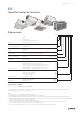
TPI 38 CFC201402


Clean areas
|
7 / 11
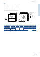
Fig. 5: Wall clean ltering cassette CFC-W
Tab. 8: Wall clean ltering cassette CFC-W
WALL - type 1 panel tting surface Filter dimensions A×B×T H
Label - dimension (mm)
CFC-W-305×610×80 305 × 610 × 80 278
CFC-W-305×610×150 305 × 610 × 150 348
CFC-W
Design and mounting properties, accessories
Clean ltering cassette design type
C B G R W
Simple front panel
tting surface
(type 2)
Mounting 1 VN, VR, AQ VN, VR, AQ
VN, VR, AQ
Mounting 4 SF, PP SF, PP
SF, PP
Front panel tting
surface with an
alignment rim
(type 1)
Mounting 1 VN, VR VN, VR VN, VR VN, VR
Mounting 4 SF, PP SF, PP
SF, PP
Including a slide-in wall ventilation grille
NA
Supply connection
Horizontal
Round Tight Untight Tight
Tight
Square
Flange
Vertical Round Tight
Tight
Filter sealing
Rubber
Gel gasket
Mounting
Ceiling
Wall
Tab. 9: An overview of the design and mounting properties and accessories
NOTE: VN, VR, AQ, SF, PP, NA = front panel diffuser types, details can be found in Tab. 10
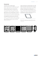
CFC-W
• Whole box hermetically welded
• Wall installation
• Flat rubber gasket lter sealing surface
• Air tight circular connection, horizontal
• Front grille slide-in xing
646
342
ø198
50 100
H
25