
TPI 38 CFC201402


2 / 11
|
Clean areas
Description
The clean ltering cassettes for clean areas are intended
for ltering the air supplied into areas with high
requirements for hygiene and dust-free environment,
such as operating rooms, intensive care units,
laboratories, dust-free manufacturing areas etc. It is
possible to install lters that have a ltration class up to
H14 with rubber sealings or gel gaskets into the ltering
cassettes for the highest possible tightness.
The design range enables clean ltering cassette
selection
• for mounting into different types of ceilings as well as
walls.
• for narrowed-down ceiling spaces with a clearance
height of 300 mm.
• for horizontal and vertical supply air ducts.
• for less challenging applications with lower price
requirements.
• for the highest requirements for supply air cleanliness
and airtightness of the ventilation elements.
• with front panels with diffuser functionality and
ventilation grilles with different air ow patterns for
installation heights up to 4m from the occupied zone.
• with an option to check the lter tightness and
clogging level by measurement, with a simple
maintenance.
Information about accessories for CFC is available
on page 9.
• VN, VR, AQ, SF, PP - Front diffuser panels
• NA - Ventilation grille
• Ledge for mounting into the ceiling
Design
Material used
All the clean ltering cassette types are manufactured
from a steel sheet with a powder lacquer surface nish,
white RAL9010 gloss 30 as standard. The structural
joints on the clean ltering cassette casings are
consistently welded to ensure the cassette airtightness
in front of as well as behind the lter.
Type B’s (basic) joints in front of the lter are spot point
welded, which means they are, from the tightness
perspective, sufcient for applications that do not require
absolute tightness.
The sealing areas for the lters are smooth for rubber
sealings for types C, B, R, W. For type G the blade
sealing area is used for the gel gasket.
The lter installation into the clean ltering cassette
and sealing pressure onto the sealing areas for types C,
B, R, W are ensured by 4 thread pressure mechanisms
in the ltering cassette corners. Type G uses 4 spring
mechanisms in the ltering cassette corners.
For a more detailed description, please see chapter
“Mounting” (page 10).
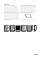
The ceiling ltering cassette types are delivered with two
types of diffuser tting surface designs – the ltering
cassette face in the tting area can be ended either with
an alignment rim (type 1) or without it (type 2).
For the type 2 tting surface, the front panels (diffusers)
are mounted either using one central bolt into the
mounting bridge, or using four bolts in the ltering
cassette corners. More specic details regarding the
tting surface types, their mounting and their purpose
assignment for different installation approaches can
be found in Fig. 8 - 10 and Tab. 1 - 7. The front panels
(diffusers) supplied along with the ceiling ltering
cassettes correspond in type names, parameters and
design with the standard Systemair diffusers.
The wall ltering cassette type is by default delivered
including a ventilation grille NOVA-A.