
Modbus Registers OPTIMA...GOMOD


Short instruction 227VM-024-05-MB
Written by: Michael Köhle Date: 13.11.2014 08:56:00 Side 5 of 13
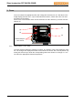
1.1.3. Display (3)
The display (3) uses 7-segment numbers in full 3-digits. Additional signs include a small
circle, three square dots and two rectangular slashes.
The square dots are used with the externally printed text to visualize certain functions or
units. It is meant to denote the unit of the value shown in the display.
If the controller tries to match reference and actual flow this is shown as flashing dot of the
chosen unit.
If the actuator is turned on (power on) and the damper position feedback is activated the
display will show REF. The actuator travels from one end-stop to the other in order to learn
the maximum angle.
The Display shows a floating average of the actual flow from the latest 4s. The refresh rate
of this value is 1s.
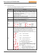
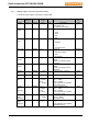
3-digit 7-segment display
Function Description
l/s
l/s
The Display shows the flow in l/s.
(see pic.)
Diag.
m³/h
Diag.
l/s
If the diagnostic mode is activated, this is
indicated by square dot. (see pic.).
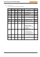
Diag.
m³/h
m³/h
l/s
The Display shows the flow in m³/h.
(see pic.)
Diag.
m³/h
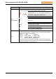
○
An overflow is indicated in the display by a small circle at the first digit.
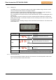
1.1.4. Declutch button (4)
Press and hold down this button and turn the actuator to the desired position. After reach-
ing the desired position release the button.