FCR230 Modbus-BACnet EN Modbus signal types 2 Modbus signals 4 Coil status register 5 Input register 6 Holding register 7 BACnet signal types 12 BACnet signals 13 1
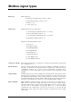
Modbus signal types EXOL types EXOL signal types: R = Floating point number (Real) (-3.3E38 - 3.
RS422 is a full duplex communication, meaning that 4 connecting wires are required; 2 for sending (Tx+ and Tx-) and 2 for receiving (Rx+ and Rx-). Tx is used for sending and Rx for receiving, meaning the Tx in a unit must be connected to the Rx in another and vice versa. Pertaining to signal levels, etc., RS422 and RS485 are identical. In order to connect RS485 and RS422: Connect Tx+ to Rx+ and Tx- to Rx- on the RS422 unit.
Modbus signals Discrete inputs Name of signal Type Modbus address Description RC_Actual_L.RegioDigIn(0) L,2 1 Not used RC_Actual_L.RegioDigIn1 L,2 2 Value on digital input 1 Not used in this model L,2 3 RC_Actual_L.RegioUDigIn1 L,2 4 Value on universal digital input 1 RC_Actual_L.RegioDigOut(0) L,2 5 Not used RC_Actual_L.RegioDigOut1 L,2 6 Value on digital output 1 RC_Actual_L.RegioDigOut2 L,2 7 Value on digital output 2 RC_Actual_L.
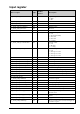
Coil status register Name of signal Type Modbus address Default value Not used in this model L,1 1 0 RC_Setp_L.RegioShutDown L,1 2 0 Puts the unit in Shutdown mode. RC_Setp_L.RegioFireAlarmStop L,1 3 0 Places the unit in Shutdown mode and prevents it from being activated again, unless this value is first set to “0”. RC_Setp_L.RegioDiNC(0) L,1 4 0 Not used RC_Setp_L.RegioDi1NC L,1 5 0 Normally open (NO) or normally closed (NC) on digital input. 0=NO, 1=NC.
Input register Name of signal Type Modbus address RC_Actual_X.RegioSoftware X,4 1 Type of Regio software: 0 = RCP 1 = RC RC_Actual_X.RegioVerMajor X,4 2 Major version RC_Actual_X.RegioVerMinor X,4 3 Minor version RC_Actual_X.RegioVerBranch X,4 4 Branch version RC_Actual_X.RegioRevision X,4 5 Revision Not used in this model X,4 6 RC_Actual_X.RegioUnitState X,4 7 Current running mode: 0 = Off 1 = Economy/Standby 2 = Not used 3 = Not used 4 = Comfort RC_Actual_X.
Holding register Name of signal Type Modbus address Default setting Not used in this model X,3 1-2 - RC_Setp_X.RegioHeatOutputSelect X,3 3 2 Manual/Auto heating output RC_Setp_X.RegioCoolOutputSelect X,3 4 2 Manual/Auto cooling output RC_Setp_X.RegioFanSelect X,3 5 4 Select fan mode: 0 = Off 1 = Manual speed 1 2 = Manual speed 2 3 = Manual speed 3 4 = Auto RC_Setp_X.
Name of signal Type Modbus address Default setting Description RC_Setp_X.RegioControllerMode X,3 18 RCFM-230Cxx =2 RCF-230Cxx = 3 Control mode selection: 2= Heating or Cooling via change-over 3 = Heating/Cooling 4 = Electric heating RC_Setp_X.RegioCVHeatType X,3 19 0 Type of actuator, heating: 0 = 0…10 V 1 = 2…10 V 2 = 10…2 V 3 = 10…0 V RC_Setp_X.RegioCVCoolType X,3 20 0 Type of actuator, cooling RC_Setp_X.
Name of signal Type Modbus address Default setting RC_Setp_X.RegioUo2 X,3 43 RCF-230CAD =4 All others = 2 Signal connected on UO2: 0 = Not used 1 = Not used 2 = Thermo valve, Cooling (not (C)AD) 3 = Not used 4 = Analogue valve Cooling (only (C)AD) RC_Setp_X.RegioModbusSlaveAddr X,3 44 Factory set Address Modbus slave RC_Setp_X.RegioModbusParity X,3 45 2 Parity and stop bits for Modbus communication: 0 = 8N2 1 = 8O1 2 = 8E1 3 = 8N1 RC_Setp_X.
Name of signal Type Modbus address Default setting RC_Setp_R.RegioUnOccSetPHeat R,3 71 15°C Heating setpoint when in Unoccupied mode RC_Setp_R.RegioUnOccSetPCool R,3 72 30°C Cooling setpoint when in Unoccupied mode RC_Setp_R.RegioFrostSetP R,3 73 N/A Not used RC_Setp_R.RegioSetpointOffsetPos R,3 74 13°C Max. upward setpoint displacement RC_Setp_R.RegioSetpointOffsetNeg R,3 75 17°C Max. downward setpoint displacement RC_Setp_R.
Name of signal Type Modbus address Default setting Description RC_SetpExt_R.RegioMaxECFanSpeed R,3 283 10 V Maximum speed of the EC fan RC_SetpExt_R.RegioRCFSetPoint R,3 284 22°C Basic setpoint RC_Setp_R.SupplyAirTLim_HeatHi R, 3 289 35°C Supply air max limitation for cascade control and heating control RC_Setp_R.SupplyAirTLim_HeatLo R, 3 290 24°C Supply air min limitation for cascade control and heating control RC_Setp_R.
BACnet signal types BACnet In order to communicate via BACnet, the protocol has to be changed either via Regio tool© or via the parameter list in the display. Once the protocol has been set to BACnet, it can only be switched back to EXOline and Modbus via the display.
BACnet signals Analogue inputs Object name Object ID Description Unit Writeable RC_Actual_R.RegioRoomTemp Analog input, 0 Room temperature °C No RC_Actual_R.RegioAIChangeOver Analog input, 1 Change-over temperature °C No RC_Actual_R.RegioAnaIn1 Analog input, 2 Value on analogue input 1 °C No RC_Actual_R.RegioUAnaIn1 Analog input, 3 Value on universal analogue input 1 V No RC_Actual_R.
Object name Object ID Description Unit Writeabl e RC_Setp_R.RegioHeatOutputManual Analog value, 13 Manual value heating output % Yes RC_Setp_R.RegioCoolOutputManual Analog value, 14 Manual value cooling output % Yes RC_Setp_R.RegioRoomTempRemote Analog value, 15 Remote control of room temperature. °C Yes RC_Setp_R.RegioStandbySetPDeadBand Analog value, 16 Deadband for Standby mode °C Yes Not used in this model Analog value, 17-26 RC_Setp_R.
Binary values Object name Object ID Description Values Writeable Not used in this model Binary value, 0 RC_Actual_L.RegioCVHeatPulsProp Binary value, 1 Indicates pulse prop. heating ACTIVE/ INACTIVE No RC_Actual_L.RegioCVCoolPulsProp Binary value, 2 Indicates pulse prop. cooling ACTIVE/ INACTIVE No RC_Actual_L.RegioCVHeatInc Binary value, 3 Indicates heating increase ACTIVE/ INACTIVE No RC_Actual_L.
Multistate inputs Object name Object ID Description Values Writeable Not used in this model Multistate input, 0 RC_Actual_X.RegioUnitState Multistate input, 1 Current running mode 1=Off 2=Economy/Standby 3=Not used 4=Not used 5=Comfort No RC_Actual_X.RegioControllerState Multistate input, 2 Current control mode 1=Off 2=Heating 3=Cooling No RC_Actual_X.
Object name Object ID RC_Non_Modbus.RegioButtonActiv Multistate value, 6 eConf Description Values Writeable Buttons active 1=No buttons Yes 2=Occupancy button only 3=INCREASE/DECR EASE only 4=Occupancy button and INCREASE/DECREA SE 5=Fan button only 6=Occupancy button and fan button 7=INCREASE/DECR EASE and fan button 8=All buttons Device The Device object contains to writeable properties; Description and Location.