
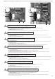
CB CBM CBMF FITTING INSTRUCTION
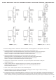


SE
GB
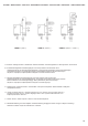
Felsökning
Trouble-shooting
Värmare typ CB
Heater models CB
Värmare typ CBM
Heater models CBM
Heater models CBMF
Full värme utan reglering
Full heating power
but no regulation
Full värme utan reglering
Full heating power
but no regulation
Ingen värme
No heating
Ingen värme
No heating
- Felet ligger ej i kanalvärmaren, kontrollera extern regulator/termostat.
- The fault is not in the duct heater. Check the external regulator/thermostat.
- Bygla/kortslut givaringången på värmarens plint, kopplas värmen bort nu så ligger felet i den externa givarkretsen.
- Givaren skall ha en resistans på 10k °C,Ω vid 30 11 k 2 °C och 15k °C (gäller givare 0...30°C).
,7 Ω vid 0 Ω vid 0
- Strap/short the sensor input on the heater terminal block. If this result in heating being turned off, then the
fault is in the external sensor circuit.
- The resistance of the sensor should be 10k @ °C,Ω 30 11. k @ 2 °C and 15k @ °C (applies to sensors
with temperature range 0...30°C).
7 Ω0 Ω0
- Kontrollera att det finns spänning fram till kanalvärmarens plint. Saknas spänning så ligger felet ej i
kanalvärmaren. Kontrollera extern regulator/termostat, säkringar, brytare, m.m.
- Finns spänning på kanalvärmarens plintar så kontrollera att det inte är avbrott i överhettningsskydd
eller element.
- Har det manuellt återställbara överhettningsskyddet löst ut, skall felorsaken undersökas innan återställning
sker. (Se under rubriken ÖVERHETTNING i början av denna folder).
- Check whether or not there is mains voltage at the heater terminal block. If there is no voltage at the terminal
block, the fault is not in the heater. Check the external regulator/thermostat, fuses, breakers, etc.
- If there is voltage at the heater terminal block, check whether the overheating cut-out or the element
is open circuit.
- When the overheating cut-out with manual reset has been activated, the fault must be investigated and
eliminated before the reset button is pressed. (See the heading OVERHEATING in the beginning of this folder).
- Kontrollera att det manuellt återställbara överhettningsskyddet ej löst ut. Eventuellt återställ efter att felorsaken
konstaterats. (Se under rubriken ÖVERHETTNING i början av denna folder).
- Kontrollmät överhettningsskydden och elementen.
- Kontrollera att det finns spänning fram till kanalvärmarens plintar.
- Kontrollera förreglingar, säkringar, brytare, m.m.
- Koppla bort givaren från värmarens plintar. Startar värmaren nu, så ligger felet i givarkretsen annars ligger
felet i regulatorn.
- Givaren skall ha en resistans på 10k °C, 11 k 2 °C och 15k °C (gäller givare 0...30°C).Ω vid 30 Ω vid 0 Ω vid 0
,7
- Check whether or not the overheating cut-out with manual reset has been activated. If it has been activated,
then eliminate the fault and reset it. (See the heading OVERHEATING in the beginning of this folder).
- Check the overheating cut-out and the elements by measurement.
- Check whether or not there is mains voltage at the heater terminal block.
- Check the interlocking devices, fuses, breakers, etc.
- Disconnect the sensor from the heater terminal block. If the heater starts now, the fault is in the sensor circuit.
Otherwise, the fault is in the regulator.
- The resistance of the sensor should be 10k @ °C, 11. k @ 2 °C and 15k @ °C (applies to sensors
with temperature range 0...30°C).
Ω30 Ω 0 Ω0
7
28
Värmare typ CBMF
-
-
Samma felsökningsförfarande som för värmare av typ CBM men dessutom:
Kontrollera att luftflödet är tillräckligt genom värmaren. Luftflödet är otillräckligt om den gula lysdioden på
kretskortet är tänd, alternativt kan luftflödet vara tillräckligt men alltför turbulent för att elektroniken skall kunna
mäta flödet som tillräckligt och då förblir den gula lysdioden tänd med utebliven värme. Dock behöver mätgivaren
ett par minuters uppvärmningstid efter att värmarens matningsspänning har kopplats till. Under denna upp-
värmningstid kommer den gula lysdioden att lysa, även om luftflödet genom värmaren är tillräckligt.
- The same procedure as above for the CBM type of heaters, but furthermore:
- Check that the airflow through the heater is sufficient. The airflow is insufficient if the yellow LED on the PCB is light
up, alternatively the airflow might be sufficient but too turbulent for the electronics to sense the airflow correctly and
then the yellow LED will remain light up and the loss of heat will also remain. However, the airflow sensing device
require a couple of minutes to heat itself after the power supply has been switched on. During that period of time
the yellow LED will remain light up, even though the airflow through the heater is sufficient.