
IMO(CE) EX 140 180
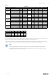
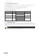


Table Of Contents

8
| Installation
5.1 Installation example
Fig. 3
Note:
Installation example (figure 3) works only as a guide for installation where the dimensioning of suspension
devices must be carried out by the installer and adapted to the prevailing conditions. Installation
components mentioned in the text are accessories that can be provided and not part of the ATEX-
certification.
Mounting the fan (3). When connected to a duct system or protective grilles fit appropriate socket on the housing (inlet
socket (2)/outlet socket (4)), then connect the duct (1) or protective grilles (5).On the fan intake section there are 4
pcs M4 threaded holes for fastening the inlet socket, screws must not protrude inside the housing (the housing thick-
ness are 5 mm).
135371 | A009