
INSTALLATION OPERATION AND MAINTENANCE INSTRUCTION ROOF FANS CE002

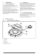


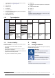


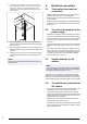
Table Of Contents
- 1Introduction
- 2Safety
- 3Transportation and storage
- 4Installation
- 5Electrical connection
- 6Commissioning
- 7Operation
- 8Maintenance
- 9Troubleshooting
- 10Disposal
- 11Warranty
- 12Technical data
- 13Accessory overview
- 14EU Declaration of Conformity
- 15UK Declaration of Conformity

3 Connect the primary electric supply to the connection
box of the product. Refer to 12.3 Wiring diagrams. For
the TFE fan, loosen the screws that hold the motor
bracket to access the terminals that are attached to the
motor bracket.
4 Pull the primary electric supply cable trough the cable
gland on the connection box and trough the cable gland
on the roof curb.
5 Use the integrated cable hose to put the primary electric
supply cable safely to the corner on the inner side of the
roof curb.
6 Install the roof curb on the roof in accordance with appli-
cable building standards and connect the fan to a duct
system.
Note:
Obey local laws and regulations for installation of the roof
curb on the roof.
5 Electrical connection
5.1 To do before the electrical
connection
• Make sure that the electrical connection agrees with the
product specification on the motor name plate.
• Make sure that the environment for electrical connection
is clean and dry.
• Make sure that the wiring diagram that is included with the
supply of the product agrees with the terminals in the con-
nection box.
5.2 To connect the product to the
power supply
• Complete the electrical connection for the motor. Refer to
the motor wiring diagram that is included with the product.
• Make sure that the cross section of the protective earthing
is equal to or larger than the cross section of the phase
conductor.
• Install a circuit breaker in the permanent electrical installa-
tion, with a contact opening of a minimum 3 mm at each
pole.
• If a residual current device (RCD) is installed, make sure
that it is an all-current sensitive RCD. Consider if the prod-
uct has a frequency converter, uninterruptible power sup-
ply (UPS), or an EC motor. EC motors have a leakage
current to earth that is <=3.5 mA.
5.3 Speed controller for AC
motors
Note:
The speed controller alternatives are different for different
motor types. Make sure that your motor is compatible with
the speed controller type before you use it.
The speed can be controlled by voltage reduction using a
transformer. It is also possible to control the fan speed with
frequency converter if the installed frequency converter has
built in all-pole sine filter and shielded cables are not needed.
5.4 To install motor protection for
AC motors
• If the product has an built in motor protection, reset by dis-
connecting the product from power for 60 seconds.
• If the motor has temperature monitors such as thermal
contacts (TK) or thermistors lead out into the terminal box,
these must always be connected in the control circuit us-
ing appropriate motor protection.
• Make sure that an overheated motor cannot start again
automatically when it becomes cool.
• Install the motor cables and the temperature monitor apart.
• If the motor does not have temperature monitors, install a
motor protection switch.
8