
211599 VTR 700 WATER HEATER INSTALLATION(A001)


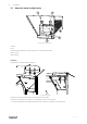
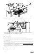
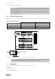


Table Of Contents

Connections
|
3
Fig. 4 Install the water heating battery
4. Secure the water heater with three previously removed knobs (pos. 1). Lead the frost protection sensor wires
through holes in the compartment walls (pos. 2) to the electrical connections compartment.
5. Connect the frost protection sensor to any free analog input on the main circuit board. Black wire should be con-
nected to ground (GND), red wire to any analog input (for example AI4).
3 Connections
3.1 Water system
When connecting a heater to the water system, the following things should be considered:
1. The connecting pipes from the water heating battery must under no circumstances be subjected to twisting or bend-
ing stresses when assembling the pipe, etc. Use suitable tools to counteract the connectors twisting/bending mo-
ments during assembly.
2. Ensure that forces due to expansion in the system and the intrinsic weight of the piping system itself do not put loads
on to the connecting pipes from the heater.
3. Hot water inlet and outlet should be connected as illustrated in figure 2. The heater contains a bleed screw (5), the
air must be properly vented from the system to ensure proper function. A venting valve should normally be installed
near the heat exchanger or at the highest point in the system.
4. A drainage screw is connected on the heater figure 2 to empty the system in the event of repair work, a longer op-
erational stop, or when there is a risk of freezing, etc.
5. Immediately after the system has been filled with water, the heater and its connections must be checked for water
leaks. Leaks can cause water damage.
Operational data:
Max. operating temperature: 125°C
211599 | A001