
VAV CAV conversion kit manual(A002)


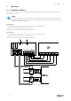

Table Of Contents

General information |
1
1 General information
The CAV/VAV duct pressure control kit is used for CAV/VAV control of SAVE residential units with touch screen control
panel. The kit includes: differential pressure transmitter (PDT12S25), installation instructions, cable set, tubes and
labels.
Important
To use CAV control, IRIS damper or a similar device with a known K-Factor have to be purchased separately.
It is not included in this package.
2 Warnings
Danger
• Make sure that the Mains supply to the unit is disconnected before performing any maintenance or
electrical work!
• All electrical connections must be carried out by an authorized installer and in accordance with local rules
and regulations.
• Beware of sharp edges during mounting.
3 Transmitter installation
1. Mount the transmitter horizontally or vertically on a stable, vibration-free surface. If the transmitter is installed in a
humid environment, install it vertically with the cable gland edge of the transmitter pointing down to allow moisture
to escape. Take extra care when connecting the hoses to the inlet ports, as the thin inner connections of the inlets
are very sensitive. The lid should be kept closed while performing the connections, or the thin tubing might detach
from the sensor.
2. Refer to the sections below for VAV and CAV wiring. Use the leftmost cable gland for supply voltage and use the
rightmost gland for output signals in order to minimise crosstalk between supply wires and signal wires.
3. Set the DIP-switches to the desired operational mode and parameters.
4. Power up the transmitter.
5. Let the transmitter warm up for 10 minutes, then perform a zero-set calibration by pressing the push-button.
Note:
Zeroing usually takes a few seconds. The yellow LED will light up while the zeroing operation is in
progress. If the yellow LED starts blinking during the zeroing procedure, the unit has failed to zero-set
properly. If so, ensure that the pressure ports are open and unobstructed and then power-cycle the unit
and try again
6. Connect plastic tubes from the ventilation duct to the pressure inlets.
3.1 DIP-swtiches
The transmitter features two groups of DIP-switches for setting up suitable pressure range, output function and damp-
ing time factor. If the DIP-switch settings are changed, all changes will take place immediately. If a factory reset is per-
formed, the pressure sensors will be reset to the factory calibration.
The leftmost DIP-switch controls sensor 1 and the rightmost DIP-switch controls sensor 2.
211528 | A002