
Modbus Registers OPTIMA...GOMOD


Short instruction 227VM-024-05-MB
Written by: Michael Köhle Date: 13.11.2014 08:56:00 Side 3 of 13
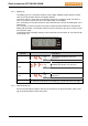
1.1.2. Function selector (2)
The function selector allows choosing the function depending on its position. If there is no
function selected the display will show three dashes (- - -).
Function Description
Flow
Shows the actual flow in m³/h, l/s and Test for diagnosis (activated Test
function). This display matches with the feedback signal U.
The display starts flashing if the servomotor hits an end stop before
matching actual to reference flow.
An overflow (higher pressure as 250 Pa = 1.0 inWC) is indicated in the
display by a small circle.
Turning the value selector allows unit selection. The appropriate dot is
toggled as indicator. The units are converted.
V
min
Allows to set the desired min. flow for the external reference signal
Y=0 V
DC
or Y=2 V
DC
. In m³/h or l/s directly of V
nom
.
V
max
Allows to set the desired maximum flow for the external reference sig-
nal Y=10 V
DC
in m
3
/h or l/s directly of V
nom
.
Mode
Allows to set the direction of rotation (normal and inverse) and the input
signal range (0…10 V
DC
or 2…10 V
DC
) of the reference signal Y. The
feedback signal range of U corresponds to Y.
0-10 V
DC
,
normal
2-10 V
DC
,
normal
0-10 V
DC
,
invers
2-10 V
DC
,
invers
Test
Opens the diagnose menu. All input signals on Y are neglected and the
controller only operates according to the selected override function. All
override functions are disabled after a time-out of 10 hours.
The display toggles after the selection of the function between the ac-
tual flow (8s showing time) and the function (2s showing time).
Selecting another function will disable the Test function and set it auto-
matically to
OFF
oP
(en) … opens the damper
cL
(ose) … closes the damper
Hi
(gh) … forces the actuator to V
max
Lo
(w) … forces the actuator to V
min
on
… Test mode is switched on.
The actuator stays in the current position.
oFF
… Test mode is switched off.
The actuator starts controlling according to external
signal Y. This signal Y shall be shown in the range
of 0…100 x10
-1
V
Adp
… adaption drive is switched on.
(only for the 15Nm version and Modbus)
123
… Showing the software version V123.
After 3s showing the display shows
oFF
again.