
INSTALLATION OPERATION AND MAINTENANCE INSTRUCTION KE KT RS RSI001
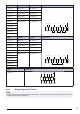
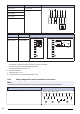
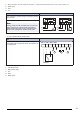
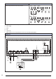
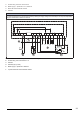
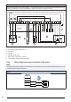

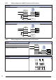
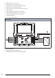
Table Of Contents
- 1Introduction
- 2Safety
- 3Transportation and storage
- 4Installation
- 5Electrical connection
- 6Commissioning
- 7Operation
- 8Maintenance
- 9Troubleshooting
- 10Disposal
- 11Warranty
- 12Technical data
- 13Accessory overview
- 14EU Declaration of conformity
- 15UK Declaration of Conformity

KT fans RS fans RSI fans 3–phase 230 V
KT 50–25–4 RS 60–35 L3 RSI 60–35 L3
TK
TK L1 L2 L3
TK TK W2 U1 U2 V1 V2 W1
KT 50–25–6 RS 60–35 M3 RSI 60–35 M3
KT 50–30–4** RS 70–40 L3 RSI 70–40 L3
KT 60-30–4 RS 80–50 L3 RSI 80–50 L3
KT 60–30–6 RS 60–35 M3 RSI 60–35 M3
KT 60–35–4 RS 100–50 L3 RSI 100–50 L3
KT 60–35–6
KT 70–40–4
KT 70-40–6
KT 80–50–6
KT 100–50–6**
KT fans RS fans RSI fans 3–phase 400 V
KT 50–25–4 RS 60–35 L3 RSI 60–35 L3
TK
TK L1 L2 L3
TK TK W2 U1 U2 V1 V2 W1
KT 50–25–6 RS 60–35 M3 RSI 60–35 M3
KT 50–30–4** RS 70–40 L3 RSI 70–40 L3
KT 60–30–4 RS 80–50 L3 RSI 80–50 L3
KT 60–30–6 RS 60–35 M3 RSI 60–35 M3
KT 60–35–4 RS 100–50 L3 RSI 100–50 L3
KT 60-35–6
KT 70–40–4
KT 70–40–6
KT 80–50–6
KT 100–50–6**
KT fans 3–phase 400 V
KT 40–20–4
TK
TK TK BU BN BK YE/GN
TK TK Z2 U2 Z1
TK L2L1 L3
12.3.2 Wiring diagrams for EC fans
Note:
An internal potentiometer is installed on the terminal block from the factory. Remove the internal potentiometer when you use
an external speed controller for the EC fan.
19