
RH CO2 Temperature sensor manual


Page 2
Wiring Diagrams
The family of products has two basic configurations. One configuration
provides three active outputs (CO
2
, RH and temperature) and an
independent thermistor. It has an output terminal block with pins
#1, 2 and 3. The other configuration provides only CO
2
outputs and an
independent thermistor and has no terminal block with pins 1, 2, and 3
installed. For electrical wiring and power supply requirements, these two
configurations are identical; please follow the specific instructions for
wiring. The recommended wire gauge is 18-22 AWG (1.0 to 0.75
metric).
!WARNING!
These products have three terminal pins that are
connected inside the sensor to a common/ground: pin
#2 and 7 on the I/O terminal blocks and pin #2 on
the
power block. Do NOT connect positive (hot) 24 VAC power
line to terminal number 2 of the terminal block.
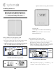
Figure 2: Display Unit Wiring for 4-Wire System, AC
Power
Caution!
These products are either 3-wire or 4-wire
type
configurations, powered by either AC or DC voltage.
They
are not 2-wire or loop-powered devices. Wiring the units
as
2-wire or
loop-powered
devices will irreparably damage
the
sensors and void the
warranty.
Note: For temperature measurements, these models contain a RTD –
PT1000 sensor (terminal pins #4 and 5), which is electrically
isolated from the other circuitry and should be wired
independently from active
CO2/RH/temperature
outputs. The
RTD has no connection to the unit’s common ground and/or
power.
The active temperature output has the same common (ground)
as CO
2
and RH outputs.
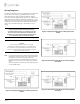
Figure 1: Display Unit Wiring for 3-Wire System, AC
Power
Figure 3: Non-Display Unit Wiring for 3-Wire System,
AC Power
Figure 4: Non-Display Unit Wiring for 4-Wire System,
AC Power
PT1000
PT1000
PT1000
PT1000