
UserManual S SA2 S SA2L202010


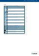


Table Of Contents
- Table of Contents
- Introduction
- Warnings
- Operating Conditions
- Installation
- Installation Methods
- Opening Preparation for S-SA2 Installation
- Standard Distances Between Damper Bodies
-  Installation into a Soft Crossing (up to Size 1000 × 800 mm)
- Connecting S-SA2 to “multi” Ductwork Made of Boards
- S-SA2L Installation
-  Installation on the Vertical Duct with a Ledge
-  Installation Directly on the Horizontal Duct
- Electrical Connections
- Operation Manual
- Smoke Damper Functionality Check
- Smoke Damper Inspection
- Warranty Conditions
- Operating Journal
- Warranty Service

6/40 | User Manual S-SA2 & S-SA2L | 201905 201905 | User Manual S-SA2 & S-SA2L | 7/40
Legend
ve Vertical supporting construction (wall, horizontal duct)
ho Horizontal supporting construction (oor/ceiling, vertical duct)
Wet Installation
Installation into a soft crossing
Damper placed on duct surface, bottom side of the duct
Damper placed on duct surface, top side of the duct
Damper placed on duct surface, left and right side of the duct
Damper placed within the duct canal, outside of supporting construction
Installation of S-SA2L on the vertical duct with a ledge
Installation of S-SA2L directly on the vertical duct
Installation of S-SA2L on the horizontal duct with a ledge
Installation of S-SA2L directly on the horizontal duct
Damper‘s horizontal blade axis orientation
- mechanism can be placed on either side
Damper‘s vertical blade axis orientation
- mechanism can be placed on top and bottom.