
UserManual S SA2 S SA2L202010
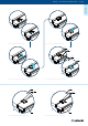
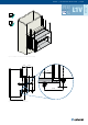
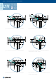
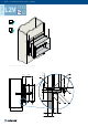
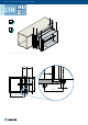
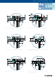
Table Of Contents
- Table of Contents
- Introduction
- Warnings
- Operating Conditions
- Installation
- Installation Methods
- Opening Preparation for S-SA2 Installation
- Standard Distances Between Damper Bodies
-  Installation into a Soft Crossing (up to Size 1000 × 800 mm)
- Connecting S-SA2 to “multi” Ductwork Made of Boards
- S-SA2L Installation
-  Installation on the Vertical Duct with a Ledge
-  Installation Directly on the Horizontal Duct
- Electrical Connections
- Operation Manual
- Smoke Damper Functionality Check
- Smoke Damper Inspection
- Warranty Conditions
- Operating Journal
- Warranty Service

S-SA2L
L1V
22/40 | User Manual S-SA2 & S-SA2L | 201905
1. Prepare the duct connection or opening as per Fig. 36 - Fig. 41, clean and atten the connecting surface.
2. Apply a re resistive coat (3) on the connection surfaces as depicted in Fig. 36 - Fig. 41.
3. Connect the damper’s ange (on the blade side) to the duct as per the
“Fixing the S-SA2L Smoke Damper”
section.
4. From boards (4 and 7) create a collar overlapping the connection as depicted in Fig. 36 - Fig. 41.
5. Fix the overlapping collar to the damper with screws (5). Fix the collar to the duct by using screws
as per instructions of duct system manufacturer.
IMPORTANT: The opening dimensions must be created according to the details of each type and thickness
of the connected duct.
The re resistivity of the S-SA2L smoke damper must be decreased to the duct performance.
The maximum resistivity for L1V installation is EI120S with pressure level 3 (-1500 Pa … 500 Pa).
1 Smoke damper S-SA2L (actuator side)
2 Connected ductwork classied according EN 1366-9
3 Fire resistive coating Promat K84 (Promat)
4 Collar made of Promatect H (Promat) - thickness per detail
5 Screw 5,5×40 DIN 7981 xing the collar with the damper
6 Screws or pins as per duct system manufacturer instructions
7 Cover plates thickness 10 mm placed on the opening circumference made of Promatect H (Promat)
8 Combi screw size 8
9 Accessory K1-S-SA2L-W×H (size of damper = W - nominal width; H - nominal height)
Damper‘s horizontal blade axis orientation
Damper‘s vertical blade axis orientation
Legend for Figures of Installation
Installation on the Vertical Duct with a Ledge