
INSTALLATION OPERATION AND MAINTENANCE INSTRUCTION TFC CE003

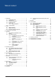

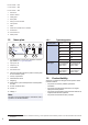
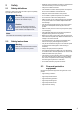

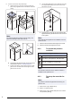

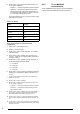
Table Of Contents
- 1Introduction
- 2Safety
- 3Transportation and storage
- 4Installation
- 5Electrical connection
- 6Commissioning
- 7Operation
- 8Maintenance
- 9Troubleshooting
- 10Disposal
- 11Warranty
- 12Technical data
- 13Accessory overview
- 14EU Declaration of Conformity
- 15UK Declaration of Conformity

B. TFC-P 225 — 280
C. TFC-S 355 — 560
D. TFC-S 225 — 280
1. Service lid
2. Electric cabinet
3. Cable gland
4. Name plate
5. Swing-out motor bracket
6. Fan impeller
7. Motor
8. Pressure controller PCA-2 1000 D2
9. Transformer
10. Connection box
11. Safety switch
1.5 Name plate
1
32
11
13
12
7
8
910
4 5 6
1. Type designation: Product name, dimension and motor
type. Refer to 1.5.1 Type designation
2. Input power, W
3. Frequency, Hz
4. Certifications
5. Scannable code
1
6. Find more information about the product on the System-
air documentation portal
1
7. Country of production
8. Airflow direction arrow
9. Weight, kg
10. Serial number: part number/production number/produc-
tion date
11. IP class, enclosure class
12. Current, A
13. Voltage, V
Note:
The data on the name plate applies to “standard air” that is
specified in the standard ISO5801.
1.5.1 Type designation
Product name TFC-P TFC-S
Dimension 225 225
280 280
355 355
450 450
500 500
560 560
Motor type EC: Electronically
commutated, 1–
phase, 230 V
EC: Electronically
commutated, 1–
phase, 230 V
EC: Electronically
commutated, 3–
phase, 400 V
EC: Electronically
commutated, 3–
phase, 400 V
1.6 Product liability
Systemair is not liable for damages that the product causes
in these conditions:
• The product is incorrectly installed, operated or
maintained.
• The product is repaired with parts that are not original
spare parts from Systemair.
• The product is used together with accessories that are not
original accessories from Systemair.
• The product is used without motor protection.
2
1. Use a mobile device to scan the scannable code and go to the Systemair documentation portal for more documentation and document
translations.