
PCA 2 1000D OPERATING INSTRUCTION25055055

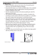
Table Of Contents

5 Electrical installation
5.1 EMC-compatible installation of control lines
Pay attention to maintain sufficient distance from powerlines and
motor wires to prevent interferences.
When using a shielded cable the shield must be connected (as
short and with as low an induction as possible!) to the PE conduc-
tor on one side at the signal input (of the evaluation unit).
5.2 Connection Voltage supply
Connection Voltage supply at terminals: “+U
S
” and “GND”. Here, it
must be strictly observedt hat the mains voltage lies within the
llowable olerance pecifications (see Technical data and nameplate
affixed to the side).
Danger due to electric current
Only PELV current sources which ensure safe electrical isolation
of the operating voltage in accordance with IEC/DIN EN 60204-1
must be used.
There is no potential isolation between supply voltage and output
signal.
5.3 Output voltage 0...10 V
Connection to terminals “A” and “GND” (I
max
see Technical data).
Parallel control of several speed controllers / EC-fans
The maximum possible number of speed controllers / EC fans with
0...10 V input that can be controlled parallel depends on their input
resistance and on the maximum admissible load of the 0...10 V
output.
Attention!
•
It is not permissible to connect outputs of several devices to
each other!
•
In case of failure of the control module or interruption of the
0...10 V specification signal, all parallel connected EC fans/-
Operating Instructions PCA-2 1000D2 Electrical installation
L-BAL-E295-GB 1906 Index 001 Part.-No.
10/48