
INSTALLATION OPERATION AND MAINTENANCE INSTRUCTION TFC CE003
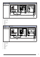
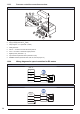
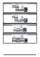
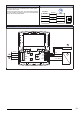
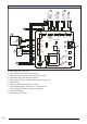
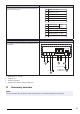
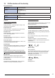
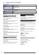
Table Of Contents
- 1Introduction
- 2Safety
- 3Transportation and storage
- 4Installation
- 5Electrical connection
- 6Commissioning
- 7Operation
- 8Maintenance
- 9Troubleshooting
- 10Disposal
- 11Warranty
- 12Technical data
- 13Accessory overview
- 14EU Declaration of Conformity
- 15UK Declaration of Conformity

12.3.3 Pressure controller connection overview
Pressure controller PCA–2 1000
4
5
6
4
9
1
2
3
7
8
1. Signal relay (terminals: 13, 14)
2. Supply voltage (terminals: U
S
, GND)
3. Output signal 0...10 V (terminals: A, GND)
4. Cable gland M16
5. “Minus” — connection in areas with lower pressure
6. “Plus” + connection in areas with higher pressure
7. Digital input D1 (terminals: 1, 2)
8. Input outdoor temperature sensor (terminals: TF, TF)
9. MODBUS interface (terminals: GND, A, B, ID1, ID2 and jumper J1)
12.3.4 Wiring diagrams for speed controllers for EC motors
MTP 10
MTP 10
1
2
4/+
3/Us
5/-
+10V
0...10V
GND
MTP 20
MTP 20
1/Vdc+
4/Vout
3/Vout-
2/Vdc-
+10V
0...10V
GND
20