english PCA-2 1000D2 Pressure sensor and pressure controller for measuring and controlling differential pressure and voume ow Operating Instructions Keep for reference! Software version: from Version 1.00 L-BAL-E295-GB 1906 Index 001 Part.-No.
Operating Instructions PCA-2 1000D2 Content 1 General notes . . . . . . . . . . . . . . . . . . . . . . . . . . . . . . . . . . . . . . . . . 1.1 Structure of the operating instructions . . . . . . . . . . . . . . 1.2 Exclusion of liability . . . . . . . . . . . . . . . . . . . . . . . . . . . . . . . 5 5 5 2 Safety instructions . . . . . . . . . . . . . . . . . . . . . . . . . . . . . . . . . . . . . 6 3 Product overview . . . . . . . . . . . . . . . . . . . . . . . . . . . . . . . . . . . . . . 3.
Operating Instructions PCA-2 1000D2 8 Programming . . . . . . . . . . . . . . . . . . . . . . . . . . . . . . . . . . . . . . . . . . 8.1 Pressure sensor 4.00 and pressure control 4.01 + 4.02 18 8.1.1 Base setup 4.00 ... 4.02 . . . . . . . . . . . . . . . . . . . 8.1.2 Settings for operation 4.01 + 4.02 . . . . . . . . . Volume sensor 5.00 and volume control 5.01 + 5.02 . 8.2.1 Base setup 5.00 ... 5.02 . . . . . . . . . . . . . . . . . . . 8.2.2 Nozzle coefficient (K-Factor) . . . . . . . . . . . . . . .
Operating Instructions PCA-2 1000D2 9.2 9.3 9.4 Connection diagram . . . . . . . . . . . . . . . . . . . . . . . . . . . . . . . Dimensions [mm] . . . . . . . . . . . . . . . . . . . . . . . . . . . . . . . . . Manufacturer reference . . . . . . . . . . . . . . . . . . . . . . . . . . . . L-BAL-E295-GB 1906 Index 001 Part.-No.
Operating Instructions PCA-2 1000D2 General notes 1 General notes Compliance with the following instructions is mandatory to ensure the functionality and safety of the product. If the following instructions given especially but not limited for general safety, transport, storage, mounting, operating conditions, start-up, maintenance, repair, cleaning and disposal / recycling are not observed, the product may not operate safely and may cause a hazard to the life and limb of users and third parties.
Operating Instructions PCA-2 1000D2 Safety instructions 2 Safety instructions Attention! • Mounting, electrical connection, and start-up operation may only be carried out by an electrical specialist in accordance with electrotechnical regulations (e.g. DIN EN 50110 or DIN EN 60204)! • Persons entrusted with the planning, installation, commissioning and maintenance and servicing in connection with the device must have the corresponding qualifications and skills for these jobs.
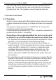
Operating Instructions PCA-2 1000D2 Product overview Any other use above and beyond this will be considered as improper use. The manufacturer will not be liable for any damage resulting from this. The company using it bears the sole risk. 3 Product overview 3.1 Function Sensor-control module with differential-pressure sensors in proven ceramic-cantilever technology for climate and clean-room application. The pressure range goes from 0...1000 Pa (0...4.0 in.wg), four measuring ranges are programmable.
Operating Instructions PCA-2 1000D2 Product overview The extended PCA -21000D2 type version provides the following additional functions: • Integrated real-time clock with timer function. • Operating modes with setpoint adjustment based on outdoor temperature and input for outdoor temperature sensor. • RS-485 interface for MODBUS RTU. • Signal relay that can be assigned different functions. 3.2 Storage • • • The device must be stored in its original packaging in a dry and weather-proof room.
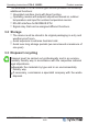
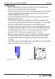
Operating Instructions PCA-2 1000D2 Mounting 4 Mounting • • • • • Bohrschablone drilling template 83 mm Gehäuse housing 111 mm • Before installation remove the device from the packing and check for any possible shipping damage! Assemble the device on a clean and stable base. Do not distort during assembly! Use the appropriate mounting devices for proper installation of the unit! Use the templates printed on the device packing to mark the fastening bore holes.
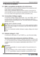
Operating Instructions PCA-2 1000D2 Electrical installation 5 Electrical installation 5.1 EMC-compatible installation of control lines Pay attention to maintain sufficient distance from powerlines and motor wires to prevent interferences. When using a shielded cable the shield must be connected (as short and with as low an induction as possible!) to the PE conductor on one side at the signal input (of the evaluation unit). 5.
Operating Instructions PCA-2 1000D2 Electrical installation speed controllers are no longer controlled. This means that all fans stop! 5.4 Digital input (D1) Different functions can be assigned to the digital input D1(see IO SETUP). A voltage at terminals “1” and “2” (10...24 V DC) activates the programmed function (note polarity - see connection diagram). 5.5 Relay outputs “K1” The relay output “K1”can have different functions assigned to it, see IO SETUP. Max.
Operating Instructions PCA-2 1000D2 • • • Electrical installation dissimilar potential (over 10 V!) will lead to the destruction of the RS-485 interface (e.g. lightning). Except the data link “A (D+)”, “B (D-)” and “GND” (for automatic addressing additional “ID1” - “ID2” see following chapter) no further cable cores of the data line may be used. Pay attention to sufficient distance from powerlines and motor wires (min. 20 cm).
Operating Instructions PCA-2 1000D2 Shield connection correct Electrical installation Shield connection incorrect When using telephone cable with four cable cores, we recommend the following allocation: • A (D+) = red • B (D-) = black • ID1 - ID2 = yellow (for automatic addressing) • GND = white Default interface parameter • Baudrate = 19200 • Bits = 8 • Parity = Even • Stop bits = 1 • Handshake = none Information Addressing is performed depending on version by display, an external terminal or a PC with t
Operating Instructions PCA-2 1000D2 Electrical installation Information • Except the data link “A (D+)”, “B (D-)” the “ID1 - ID2” and the “GND” connection may no further cable cores of the data line be used. • The connections for the automatic addressing “ID1” and “ID2” are not directly connected with each other internally. These may not be bridged; any order of connection is possible.
Operating Instructions PCA-2 1000D2 6 Device construction 6.1 Connecting elements 1 2 3 4 5 6 7 8 9 Signal relay (terminals: 13, 14) Supply voltage (terminals: US, GND) Output signal 0...
Operating Instructions PCA-2 1000D2 Modes/Start-up Messages on the display OFF No enable Exceeding measuring range ! Moon symbol = Adjustment for Setpoint 2 active Hourerglass symbol = Timer function active External error Limit Uout Limit Pressure External fault alarm Limit: Modulation Limit: Pressure Limit AirVolume Limit: volume flow Limit: Temperature Limit Temp. Check Temp Sens Failure: Check temperature sensor Check Press Sens Failure: Check pressure sensor 7 Modes/Start-up 7.
Operating Instructions PCA-2 1000D2 Mode 5.02 Modes/Start-up Function Volume flow control (PID) with outdoor temperature compensation: output 0...10 V depending on adjusted setpoint, outdoor temperature and measured actual value. 7.2 Start-up Procedure 1. You must mount and connect the device in accordance with the operating instructions. 2. Double check that all connections are correct. 3. The supply voltage must match the information on the rating plate. 4.
Operating Instructions PCA-2 1000D2 Programming Example for Mode 4.01 (Factory setting) ▼ ▲ INFO P↓ ↑ Esc ▼ ▲ SETTING P↓ ↑ Esc 100 Pa Δp BASE SETUP P↓ ↑ Esc 100 Pa Setpoint 1 ▲▼ ▲▼ 100 Pa Setpoint 1 ▲▼ 100 Pa Setpoint 2 ▲▼ 4.01 Mode ▲▼ 1: metric Units ▲▼ Reprogramming Mode 4.01 to 5.00 in “BASE SETUP” 1 2 4.01 Mode 3 «4.01» Mode P 4 ▲ 5 «5.00» Mode 6 7 P 5.00 Mode 8 Programming 8.1 Pressure sensor 4.00 and pressure control 4.01 + 4.02 8.1.1 Base setup 4.00 ... 4.
Operating Instructions PCA-2 1000D2 Programming Temperature sensor for recording the outdoor temperature in KTY81-210 4.02 operating mode. Sensor type: KTY 81-210 (factory fitTemp. Sensor ted) or PT 1000. 0...1000 Pa Measuring range OFF Autozero 1: 0...1000 Pa (0...4.0 in.wg) 2: 0...500 Pa (0...2.0 in.wg) 3: 0...300 Pa (0...1.2 in.wg) 4: 0...200 Pa (0...0.8 in.
Operating Instructions PCA-2 1000D2 Programming 8.1.2 Settings for operation 4.01 + 4.02 SETTING 500 Pa (22.0 in.wg) Setpoint 1 500 Pa (2.0 in.wg) Setpoint 1 500 Pa (2.0 in.
Operating Instructions PCA-2 1000D2 Programming Outside-temperature dependent target-setpoint [Pa] S1 S2 P-min. AT -15 °C T-min. T-Band 30 °C T-Start 18.09.2014 v_pressure_set_dep_outtemp.vsd S1 Setpoint1 S2 Set Internal2 P-min. Min. Setpoint T-min Min. temperature T-Start Setpoint reducing will start below this outside temperature T-band Temperature range AT Outdoor temperature 30.0 K (54.0 °F) T-Band SA 15.0 °C (59.
Operating Instructions PCA-2 1000D2 Programming 8.2 Volume sensor 5.00 and volume control 5.01 + 5.02 8.2.1 Base setup 5.00 ... 5.02 BASE SETUP 5.01 Mode 5.00 : Volume flow sensor 5.01 : Volume flow control 5.02 : Volume flow control with outdoor temperature compensation metric Units Display in SI units "metric" (factory setting) or Imperial units (US) "inch". Conversion factors: Pressure: 1.0 in.wg = 254 Pa Volume flow: 1.0 cfm = 0.5885 m3/h (inlet ring: K-Faktor US = 9.3 x K-Factor SI) Temperature ( 4.
Operating Instructions PCA-2 1000D2 OFF Autozero Programming If the actual value is not “0 Pa Δp” in pressureless state a zero-point adjustment is possible with fuction “Autozero”. This may be necessary, for example, in case of heavy thermal fluctuations in the sensor environment or non-vertical mounting. Proceed as follows: 1. Pull off the pressurised hoses. 2. Switch function “Autozero” to “ON”. 3.
Operating Instructions PCA-2 1000D2 Programming 3 Air flow measuring range: max. 65000 m /h (38257 cfm) depending on setting of measuring range and K-Factor. 8.2.3 Setting for operation 5.01 and 5.
Operating Instructions PCA-2 1000D2 Programming Additional menu item for mode 5.02 with outside-temperature dependent target-setpoint Outside-temperature dependent target-setpoint [m3/h] S1 S2 V-min. AT -15 °C T-min. T-Band 30 °C T-Start 20.09.2017 v_volume_set_dep_outtemp.vsd S1 Setpoint1 S2 Set Internal2 V-min. Min. Setpoint T-min Min. temperature T-Start Setpoint reducing will start below this outside temperature T-band Temperature range AT Outdoor temperature 30.0 K (54.0 °F) T-Band SA 15.
Operating Instructions PCA-2 1000D2 Programming 8.3 Menu group "INFO" The number of menus depends on the selected operating mode. Settings cannot be made in this menu group! INFO Mode Display 4.00 4.01 4.02 5.00 5.01 5.02 Actual value after turning on the voltage or after exiting the setting menu using the Esc key combination. 0 Pa 0 Pa 0 Pa Δp (0.000 in.wg) (0.000 in.wg) (0.000 in.wg) qV - - - - 15.
Operating Instructions PCA-2 1000D2 Programming Mode Display 4.00 4.01 4.02 Magnitude of the output voltage 0...10 V Uout 0.0 V 9.9 V 9.9 V 5.00 5.01 5.02 0.0 V 9.9 V 9.9 V Display actual value for volume measurement 0 Pa 0 Pa 0 Pa Δp - - - (0.000 in.wg) (0.000 in.wg) (0.000 in.wg) Time - 8:54 8:54 - 8:54 8:54 1.00 1.00 1.00 1.00 1.00 1.00 Time Software version XXX 8.4 Menu group "IO SETUP" 8.4.
Operating Instructions PCA-2 1000D2 Virtual IOs Pool real IOs (signal sources) AO1 Analog output • Analog output A1 (terminals: A, GND) DO1 Digital output • Relay output K1 (terminals: 13, 14) Programming DI1 - DI3 • Digital input D1 (terminals: 1, 2) Digital inputs • Timer from time switch (for 4.00 and 5.00 not • MODBUS interface (terminals: A, B) available) If only one signal source is available, no further assignment is possible (n.a. = no assignment). 8.4.
Operating Instructions PCA-2 1000D2 Programming 8.4.3 Digital output “DO” Menu overview Function Designation Fault indic. 2K Setting of the desired function (see following table). DO1 Function Relay output K1 (terminals: 13, 14) K1 No further assignment possible, n.a. (no assignment) = No DO1 Signal signal assigned. Inverting output OFF DO1 Inverting Setting of the desired function Function K1 OFF Designation No function Relays remain always de-energized. Operating indication Operation indic.
Operating Instructions PCA-2 1000D2 13 K1 1 = energized, terminals 13 - 14 bridged 0 = de-energized, terminals 13 - 14 not bridged 14 K1 Programming 10.11.2008 v_relais_k1_13_14.
Operating Instructions PCA-2 1000D2 Programming 8.4.4 Digital inputs “DI” The device has three virtual digital inputs: DI1, DI2 and DI3 (not available in 4.00 and 5.00 ). 8.4.4.1 Menu overview Example for DI1 Function OFF DI1 Function n.a. DI1 Signal OFF DI Inverting Designation Setting of the desired function (see following table). Allocation: virtuell input <=> real input • n.a.
Operating Instructions PCA-2 1000D2 8.4.4.2 Programming Enable ON/OFF, function |1D | Remote ON/OFF (electronic disconnection). The device can still be operated in the switched-off state after pressing the “Esc” key combination. A programmed alarm relay (factory set “K1 function” = |2K | ) does not report the switch-off.
Operating Instructions PCA-2 1000D2 100 Pa Δp Programming External message display alternating with the actual value display External Error Δp Possible controls Real input Inverting DI State input Digital input D1 (terminals: 1, 2) OFF ON Timer from time switch OFF External Error Voltage ON YES Voltage OFF NO Voltage ON NO Voltage OFF YES Timer active YES Timer not active NO Timer active ON YES Register H01 Bit 15 not set MODBUS interface (terminals: A, B) OFF ON 8.4.4.
Operating Instructions PCA-2 1000D2 Programming Possible controls Real input Inverting DI State input Digital input D1 (terminals: 1, 2) OFF ON Timer from time switch OFF ON MODBUS interface (terminals: A, B) OFF ON active Voltage ON Setpoint 2 Voltage OFF Setpoint 1 Voltage ON Setpoint 1 Voltage OFF Setpoint 2 Timer active Setpoint 2 Timer not active Setpoint 1 Timer active Setpoint 1 Timer not active Setpoint 2 Register H01 Bit 15 not set Setpoint 1 Register H01 Bit 15 set Se
Operating Instructions PCA-2 1000D2 Programming Example message by relay “K1”: not inverted IO Setup: K1 Function = 4K IO Setup: K1 Inverting = OFF Inverting IO Setup: K1 Function = 4K IO Setup: K1 Inverting = OFF 1 1 0 0 min max 100 % A min 100 % A 1 1 0 0 max A max min 100 % A max 11.05.2007 v_grenzwert_ausst_k1_ni.vsd A Modulation min 100 % A 11.05.2007 v_grenzwert_ausst_k1_i.vsd Modulation If "Level min." is higher than "Level max." , the "Level max.
Operating Instructions PCA-2 1000D2 0 Pa / 0 m3/h (in.wg / cfm) Value min. 0 Pa / 0 m3/h (in.wg / cfm) Value max. 2s Value delay Programming Work can be carried out with one as well as with both limit indicators. If the actual value undercuts the set value "Value min.", this is reported until the set value (plus 5 % hysteresis) has been exceeded once again. If the actual value exceeds the set value "Value max.", this is reported until the set value (minus 5 % hysteresis) has been undercut once again.
Operating Instructions PCA-2 1000D2 Programming 8.5.3 Limit message outdoor temperature Function is only available in operating modes 4.02 and 5.02 . Menu overview Function OFF Actual Temp Fnc -50.0 °C (-58.0°F) Temp min. 150.0 °C (302.0°F) Temp max. 2s Temp delay Designation OFF: no function ON: limit message active The values "Temp min." and "Temp max" can be set independent of each other. The "Limit Temp.
Operating Instructions PCA-2 1000D2 Programming Examples for limit messages outdoor temperature 1 1 0 Analog IN 50 % 100 % 50 % 100 % 50 % 100 % 11.05.2007 v_grenzwert_signal_k1_1.vsd 1 2 0 Analog IN 11.05.2007 v_grenzwert_signal_k1_2.vsd 1 3 0 Analog IN 11.05.2007 v_grenzwert_signal_k1_3.vsd Settings - Temp. Max.: 80 °C - Temp. Min.: OFF - switching hysteresis 5 % (from 100 %) Settings - Temp. Min.: 20 °C - Temp. Max.: OFF - switching hysteresis 5 % (from 100 %) Settings - Temp. Min.
Operating Instructions PCA-2 1000D2 Programming Menu overview Parameter 15:05 Time Designation Time Press the P-key and set the hours with the UP / DOWN keys, press the P-key to save. Now the minutes flash and can be set with the UP / DOWN keys, press the P-key to save. 25.09.17 Date Date To set the date follow the same method as for “Time”. The date setting consists of day,month and year. Example for: 25. September 2017 Entering the date is only required if automatic summer time adjustment is used.
Operating Instructions PCA-2 1000D2 Programming 8.7 MODBUS SLAVE 8.7.1 Address and interface parameters Addressing and configuration of the MODBUS Slave interface. Via this interface the device can be networked with a master building control system, the device then operates as a pure Slave and uses the MODBUS-RTU protocol. The connection is made to the terminals “A (D+)”, “B (D-)” of the MODBUS Slave interface (see installation / RS-485 interfaces for MODBUS RTU).
Operating Instructions PCA-2 1000D2 Programming 8.7.2 MODBUS Register 8.7.2.1 Holding register Mode HR H00 Function/Setting 4. 5. 00 01 02 00 01 02 x H01 H02 x x x x x x x x x x 0 = OFF x 1 = Restore factory setting (delivery status) x Input MODBUS, digital control bit wise* x Digital inputs DI1-3 @ Bit 15, relay K1 @ Bit 14 x On register H23 Value 2 = Function 17A: Preset output voltage from analog output “AO” with assignment “A1”: x 0...100 0...10 V Bus address: 1...247 @ Bit 8...
Operating Instructions PCA-2 1000D2 Programming Mode HR 4. 5. Function/Setting 00 01 02 00 01 02 H18 x x x H19 x x x H20 x x x H21 x x x H22 x x x x DI2 function: 0 = OFF, 1 = 2D, 2 = 2D, 3 = 5D DI2 Signal: 0 = n.a. (no asignement), 1 = D1, 2 = x MODBUS, 3 = Timer x DI3 function: 0 = OFF, 1 = 1D, 2 = 3D, 3 = 5D DI3 Signal: 0 = n.a.
Operating Instructions PCA-2 1000D2 Programming Mode HR 4. 5. Function/Setting 00 01 02 00 01 02 H42 x Start temperature setpoint lowering: x -100...400 -10.0...40.0 °C (-140...1040 14.0...104.0 °F) H43 x Minimum Setpoint: 0...max. measuring range (Pa, x in.wg, m3/h, cfm) H44 x x x x x Units of the display: 0 = SI units "metric", 1 = Imperial units x (US) "inch" H45 x x x x x Measuring range: 0/1/2/3 : x 200/300/500/1000 Pa (0.8/1.2/2.0/4.0 in.
Operating Instructions PCA-2 1000D2 8.7.2.2 Programming Input register Mode IR 4. 5. Information 00 01 02 00 01 02 x Software version: 100 = 1.00 x Product code: 0h0508 I00 x x x x x I01 x x x x x I03 x x x x x I04 x x x x x I05 x x x x x I06 x x x x x x Unique device Signature 0...5 x Unique device Signature 0...
Operating Instructions PCA-2 1000D2 Enclosure 9 Enclosure 9.1 Technical data Type PCA-2 1000D2 Part-No. 93347 (320076-42) Voltage supply 10...24 V DC (+20 %) Protected against reverse polarity @ US 10 V DC @ US 13...24 V DC Max. load output 0...10 V (short-circuit-proof) 0.3 mA 10 mA Max. current consumption ca. 28 mA 28 mA Pressure connections “+, -” Hose connectors d = 5 / 6 mm (0.20 / 0.
Operating Instructions PCA-2 1000D2 Enclosure Accuracy and measuring ranges 0...1000 Pa Pressure measuring range max. (0...4.0 in.wg) Tolerance zero point max.*) % +/- 0.9 Tolerance full scale max. % +/- 1.3 Resolution % 0.1 Total of linearity, hysteresis and repeatability max. % 0.6 Long term stability according to DIN EN 60770 % +/- 1.0 Temperature coefficient typical %/ 10K +/- 0.2 Temperature coefficient max. %/ 10K +/- 0.
Operating Instructions PCA-2 1000D2 Enclosure 9.2 Connection diagram PCA-2 1000D2 Kontaktbelastung 7 Contact rating max. AC 250 V 2 A p 13 14 +US GND A GND K1 MODBUS Slave Ri = 4 kΩ PI V 1(+) 2( ) TF A1 TF A B ID1 GND (D+) (D-) A B ID2 GND (D+) (D-) J1 D1 + TF.. 3 Spannungsversorgung Voltage supply 10...24 V DC (10...24 V: Imax = 28 mA) 01 q KTY 81-210 PT 1000 + 10...24 V DC + Uout Ausgang Output 0...10 V (Imax = 0.3 mA @ US 10 V) (Imax = 10 mA @ US 13...
Operating Instructions PCA-2 1000D2 Enclosure 9.4 Manufacturer reference Our products are manufactured in accordance with the relevant international regulations. If you have any questions concerning the use of our products or plan special uses, please contact: Systemair Industrievägen 3 73930 Skinnskatteberg Telefon:+46 (0) 222 440 00 Telefax:+46 (0) 222 440 99 mailbox@systemair.se www.systemair.se L-BAL-E295-GB 1906 Index 001 Part.-No.