
PCA 2 1000D OPERATING INSTRUCTION25055055
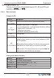
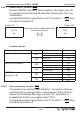
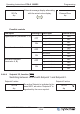
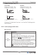
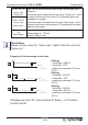
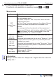
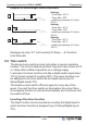
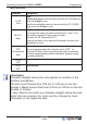
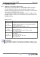
Table Of Contents

8.4.4 Digital inputs “DI”
The device has three virtual digital inputs: DI1, DI2 and DI3 (not
available in
4.00 and 5.00 ).
8.4.4.1 Menu overview
Example for DI1
Function Designation
OFF
DI1 Function
Setting of the desired function (see following table).
n.a.
DI1 Signal
Allocation: virtuell input <=> real input
•
n.a. (no asignement) = no signal assigned (factory setting)
•
Digital input D1 (terminals: 1, 2)
•
Timer from time switch
•
MODBUS interface (terminals: A, B)
OFF
DI Inverting
Inverting input
OR
DI - DI Relation
If the digital inputs have the same function allocation (also
applies for timer function) you can choose between an AND
and OR operation.
OR operation (factory setting). The function becomes active
when one of the digital inputs or the timer is activated.
AND operation. The function becomes only active when all
digital inputs or also the timer are activated.
Setting of the desired function
Function Designation
OFF
no function (factory setting)
Enable 1D
Enable (remote control) “ON” / “OFF”
Extern Error 2D
External fault alarm
Setpoint 1/2 5D
Switch over “Setpoint1” / “Setpoint2”
Operating Instructions PCA-2 1000D2 Programming
L-BAL-E295-GB 1906 Index 001 Part.-No.
31/48