
Installation and operating instructions


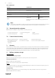
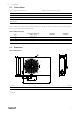
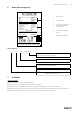
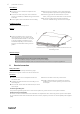
Table Of Contents
- 1 General information
- 2 Important safety information
- 3 Warranty
- 4 Delivery, transport, storage
- 5 Description
- 6 Name plate and type key
- 7 Installation
- 8 Electrical connection
- 9 Commissioning
- 10 Operation
- 11 Troubleshooting/maintenance/repair
- 12 Cleaning
- 13 Deinstallation/dismantling
- 14 Disposal
- 15 Commissioning Report

6
| Electrical connection
Preconditions
♦ Ensure that the fan and all its components are
undamaged.
♦ Fit the fans in such a way that there is sufficient
access for installation, troubleshooting, maintenance
and repair.
♦ Protect against dust and moisture when installing.
♦ Ensure that the information on the name plates (fan
and motor) matches up with the operating conditions.
♦ A warning sign must be attached close to the air
outlet, stating that the air outlet must not be covered.
♦ Fit the fans in such a way that there is sufficient
access for troubleshooting, maintenance and repair.
Installation positions
Always install in a horizontal position.
Deflector
♦ Position the deflector fins so that after
fastening the jet fan to the ceiling, the air
flow is directed downwards at a 10° angle.
It may be possible to readjust the fans
afterwards depending on the structures
located in the immediate vicinity, such as
girders.
IV
D
Position the fins to specified angle and secure them with 4.2 x 13
self-drilling screws.
Vibration dampers
Important
Risk of damage to the fan due to incorrect vibration dampers
♦ Use the vibration dampers suitable for the respective weight.
♦ Use the vibration dampers with fire resistance classes that match the respective application.
8 Electrical connection
Safety information
♦ Observe 2 Important safety information, page 1
♦ Prevent the ingress of water into the connection box.
Connection
♦ Check if the data on the nameplate matches the
connection data.
♦ Complete the electrical connection according to the
circuit diagram.
♦ Fans with EC- motors must be switched on/off via the
control input.
♦ Connect the cable end in a dry environment.
♦ Install a circuit breaker in the permanent electrical
installation, with a contact opening of at least 3 mm
at each pole.
Protective grounding wire
The protective grounding must have a cross-section equal to or greater than that of the phase conductor.
Residual current circuit breaker
All-current-sensitive residual current circuit breakers are required for use in alternating-current systems with 50/60
Hz, in combination with electronic devices such as EC motors, frequency converters or uninterruptible power supplies
(UPS).
| 003