
Installation, Operation and Maintenance instruction 001
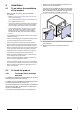
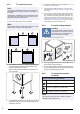
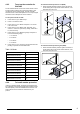
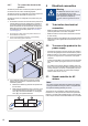
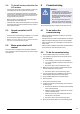
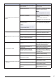
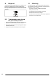
Table Of Contents
- 1Introduction
- 2Safety
- 3Transportation and storage
- 4Installation
- 5Electrical connection
- 6Commissioning
- 7Operation
- 8Maintenance
- 9Troubleshooting
- 10Disposal
- 11Warranty
- 12Technical data
- 13Accessory overview
- 14EU Declaration of Conformity-Multibox
- 15EU Declaration of Conformity-Multibox+Filter
- 16EU Declaration of Conformity-Thermo fans
- 17EU Declaration of Conformity-Smoke extract fans
- 18UKCA Declaration of Conformity-Multibox
- 19UKCA Declaration of Conformity-MUB+Filter
- 20UKCADeclaration of Conformity-Thermo fans
- 21UKCA Declaration of Conformity-Smoke extract fans

4 Installation
4.1 To do before the installation
of the product
• Make sure that you have the necessary installation
accessories:
– Refer to 13 Accessory overview page 33 for an over-
view of the accessories.
– If you install the product outdoors, it is necessary to in-
stall a weather protection roof.
– To decrease vibrations transmitted from the product to
the duct system, Systemair recommends to install vi-
bration dampers, fast clamps or flexible connections.
– If you install the product with free suction or free dis-
charge, it is necessary to install a protection grille.
Make sure that the safety distance agrees with the
standard DIN EN ISO 13857 and the standard DIN
24167–1.
• Use installation material with fire resistance rating for the
installation location.
• Examine the packaging for transportation damage and re-
move the packaging from the product carefully.
• Examine the product and all components for damage.
• Make sure that the motor effect and the fan performance
agrees with the expectations at the installation location.
• Make sure that the information on the name plate and the
motor name plate agrees with the operation conditions.
• Install the product in a location where there is space for
commissioning, troubleshooting and maintenance.
• Make sure that the installation location is clean and dry,
for full safety during electrical work.
• Make sure that the installation surface has sufficient ca-
pacity to hold the weight of the product.
• Refer to the airflow direction arrows on the name plate or
on the product to install the product in the correct position.
• Make sure that all cable glands are tight against the ca-
bles to prevent leaks.
4.2 To install the product
4.2.1 To change the air discharge
direction
The MUB fan, the MUB/T-S fan and the MUB/F fan are deliv-
ered prepared for inline airflow discharge.
The MUB/T fan and the MUB/T ECO are delivered prepared
for upward airflow direction discharge to 90°.
The air discharge direction can be changed on the MUB fans,
the MUB-CAV/VAV fans, the MUB/T fans, the MUB/T ECO
fans and on the MUB/F fans.
To change the air discharge direction, follow these steps:
1 Remove the 4 screws that attach the side panel to the
frame and remove the side panel.
The picture shows the MUB/T fan which has the locking
system for the panel shown. The MUB fans, the MUB/T
fans, the MUB ECO fans and MUB/F fans have no lock-
ing system or handle, only screws in the frame.
2 Place the side panel on the side of the fan where airflow
is to be blocked.
3 Attach the side panel to that side frame with the 4
screws.
7