
Installation, Operation and Maintenance instruction 001
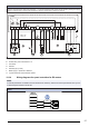
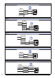
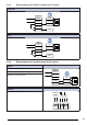
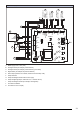
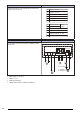
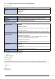
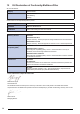
Table Of Contents
- 1Introduction
- 2Safety
- 3Transportation and storage
- 4Installation
- 5Electrical connection
- 6Commissioning
- 7Operation
- 8Maintenance
- 9Troubleshooting
- 10Disposal
- 11Warranty
- 12Technical data
- 13Accessory overview
- 14EU Declaration of Conformity-Multibox
- 15EU Declaration of Conformity-Multibox+Filter
- 16EU Declaration of Conformity-Thermo fans
- 17EU Declaration of Conformity-Smoke extract fans
- 18UKCA Declaration of Conformity-Multibox
- 19UKCA Declaration of Conformity-MUB+Filter
- 20UKCADeclaration of Conformity-Thermo fans
- 21UKCA Declaration of Conformity-Smoke extract fans

EC-Vent
Demand control for up to 5 external sensors, 2 fans, damp-
ers, heaters and coolers.
The EC vent system has 2 units. The control board (CB) and
the room unit (RU). Connect the fan to the control board and
remove the internal potentiometer.
EC-Vent
IN/RPM
PWM
IN/10V
OUT/PWN
GND
TACH
optional
+10V
0...10V/PWM
GND
Room Unit (RU)
Br + 24VDC
Y +0-10V
Gr-
Bl (GND)
R+ 24VDC
Y +0-10V
W -
CB
A
B
GND
24V
REF
T1
I2
I1
24V
C
B
A
30