
ACCESS QUICK CONFIG GUIDE SW 4 0 1 05 157618
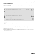
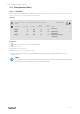

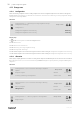
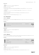

Table Of Contents
- 1 About this document
- 2 How to set up a function
- 3 Save commissioning settings
- 4 Quick configuration guides
- 4.1 Editable naming
- 4.2 Alarm configuration
- 4.3 Fan control type (Pressure)
- 4.4 Temperature control type (Room)
- 4.5 Extended operation
- 4.6 Fan compensation
- 4.7 CO2 control (Fan start/stop)
- 4.8 Fire/Smoke function (Fire)
- 4.9 Free cooling
- 4.10 External cooler (DX)
- 4.11 External heater (Water)
- 4.12 Change over
- 4.13 External stop
- 4.14 Support control

Quick configuration guides |
29
Step by step:
1.
Select Configuration from the navigation icons
2. Select I/O allocation settings
3. Select Digital inputs
4. Select the input connected to the heating/cooling feedback (e.g. DI4) as position for Cooling/(Heating)
changeover 1
5. Go back to I/O allocation settings (use the navigation path Configuration > I/O allocation
settings)
6. Select Analog outputs
7. Select the analog output connected to the control signal (e.g. AO4) as position for Changeover 1
8. Select Changeover 1
9. Adjust Range output to the desired voltage range (e.g. 0-10 V).
4.13 External stop
4.13.1 Activation
Set External stop to Yes in the list of available functions in the Configuration > Functions > Function ac-
tivation menu.
Overview:
Configuration > Functions > Function activation
04 Apr 13:54
External stop
Yes
Step by step:
1.
Select Configuration from the navigation icons
2. Select Functions
3. Select Function activation
4. Select Yes as External stop.
4.13.2 Allocation
Select the I/O (in-output) placement of where the external stop switch is connected to the controller in the Configu-
ration > I/O allocation settings > Digital inputs menu.
Overview:
Configuration > I/O allocation settings > Digital
inputs
04 Apr 13:54
Digital inputs
Device Position
External stop
Controller
DI6
Step by step:
1.
Select Configuration from the navigation icons
2. Select I/O allocation settings
3. Select Digital inputs
4. Select the input connected to the external stop switch (e.g. DI6) as position for External stop.
157618 | A002