
Operation and Maintenance Instructions
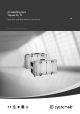


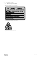
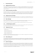
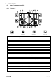
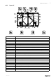
Table Of Contents
- 1 Overview
- 2 Warnings
- 3 Warnings signs on product
- 4 Product description
- 5 Start up
- 6 Operation
- 7 Maintenance
- 7.1 Maintenance intervals
- 7.2 How to replace supply/extract air filter
- 7.3 How to clean NaviPad
- 7.4 How to clean the heat exchanger
- 7.5 How to clean the fans
- 7.6 How to clean hot water heating coil
- 7.7 How to clean the electric heating coil
- 7.8 How to clean the extract air louvres and inlet diffusers
- 7.9 Clean the outdoor air intake
- 7.10 How to clean the duct system
- 7.11 Where to reset tripped fuses
- 7.12 How to reset the manual overheat protection (EL units)
- 7.13 How to replace the fan module
- 7.14 How to replace the heat exchanger
- 7.15 Change the internal battery in control unit CU27–C
- 8 Troubleshooting
- 9 Alarms
- 10 Service
- 11 General conditions
- 12 Spare parts

Product description |
3
4 Product description
4.1 Supply and extract air fans
The fans have external rotor motors of EC type which are steplessly controlled individually by setting the control signal
to a fixed value. It is possible to program the speed in 3 steps (high/normal/low) depending on the programming of the
week schedule. The motor bearings are maintenance free. It is possible to remove the fans for cleaning, see chapter 7
for more information.
4.2 Pressure transmitter fans/filters
Two pressure transmitters are installed, each of the transmitters has two sensors. One sensor measure the differential
pressure over the inlet cone of the fan impellers to maintain the airflow at constant level (CAV function as standard).
The other sensor measure the differential pressure over the supply and extract air filters. When the pressure drop rea-
ches the set value, an alarm is triggered in Access control unit, which indicates that the filter needs to be replaced.
4.3 Supply and extract air filters
The filters are of bag filter type with filter quality ePM1 60% (F7) for the supply air filter and ePM10 60% (M5) for the
extract air filter. The filters need to be replaced when polluted. We recommend ordering original filters from Systemair.
4.4 Heat exchanger
Topvex SC, TC models are equipped with a counter flow heat exchanger and a by-pass damper. The operation of the
by-pass damper is automatic and depends on the set temperature or if defrosting is in operation.
For defrosting a pressure transmitter is installed which measure the differential pressure over the heat exchanger.
4.4.1 VDI 6022 Hygiene standard
If an operation stop of the air handling unit for more than 48 hours is planed, we advise against using cooling recovery.
This is to avoid microbial growth in eventual condensation water in the supply air.
4.5 Temperature sensor
4 temperature sensors (PT1000) are included in the unit from factory. The sensors are as follows:
• Supply air sensor
• Extract air temperature sensor
• Outdoor air temperature sensor
• Exhaust air temperature sensor
• Efficiency temperature sensor
The supply air sensor is loosely delivered with the unit and needs to be installed in the supply air duct externally from
the unit. See Installation instructions for more information.
4.6 Water heating coil
In air handling units with built in water heating coil the hot water coil is located next to the supply air connection. The
hot water coil can be either HWL (hot water coil, low power) or HWH (hot water coil, high power). The coil material is
copper piping with a frame of galvanized sheet steel and aluminium fins. The coil is equipped with venting and immer-
sion sensor for frost protection.
4.7 Electric heating coil
In air handling units with built in electrical heater the heating rods are located after the supply air fan in the airflow di-
rection. The material is stainless steel. The electrical heating coil has both automatic and manual overheating protec-
tion. Reset the manual overheat protection by pushing the red button on top of the electrical heater frame (figure 8).
The electrical heater is mechanically interlocked by an air flow sensor in the supply air. The power demand of the elec-
tric heating coil is controlled by Access control unit. The heat is controlled steplessly by a TTC triac control according to
the selected control function that is set in NaviPad control panel.
214959 | A007