
INSTALLATION OPERATION AND MAINTENANCE INSTRUCTION ZRS CE002
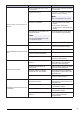
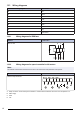
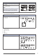
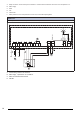
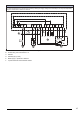
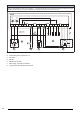
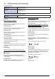
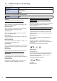
Table Of Contents

12.3 Wiring diagrams
Abbreviation in wiring diagram Cable colour
RD Red
YE Yellow
BU Blue
WH White
GN Green
BN Brown
BK Black
GR Grey
GY Green/Yellow
12.3.1 Wiring diagrams for ZRS fans
ZRS fans 1–phase 230 V
ZRS 170–180
BN
BU
BK
GY
C
N L
12.3.2 Wiring diagrams for speed controller for AC motors
Note:
The selection of electrical accessories must be done in line with the technical parameters of the product.
RE
Manual 5-step transformer.
RE 1,5
N N N
RE 3 RE 5 RE 7
~ ~
DCBA
A. Relay connection. There is always 230 V between ~ and N when the transformer knob is in one of the positions 1–5.
B. Mains supply
C. Earth
D. Fan
12