Topvex FC Topvex FC Compact AirAir Handling Compact Handling Unit Unit Compact Air Handling Unit Operation and Maintenance Instructions Operation and Maintenance Instructions V1 (2/2) Document in original language Document in original language 125918-EN_GB 2015-03-16 A001 125918-EN_GB 2015-03-16 A001
Contents Topvex FC 1 Warnings........................................................................................................................................................... 1 2 Product Description........................................................................................................................................... 2 2.1 Internal components .............................................................................................................................. 2 2.
Danger • • Topvex FC Make sure that the Mains supply to the unit is disconnected before performing any maintenance or electrical work! All electrical connections must be carried out by an authorized installer and in accordance with local rules and regulations. Compact Air Handling Unit Warning • • • • • The door handles are only intended to be used during the installation and service. These must be removed before the unit is put into operation to ensure the required level of safety for the unit.
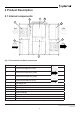
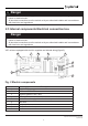
2 Product Description Topvex 2.1 Internal components 5 8 FC 6 Compact Air Handling Unit 1 SUP 3 ODA 2 4 ETA ETA 7 Fig.
2.2 Description of internal components 2.2.1 Supply and Extract air Fans Topvex FC The fans have external rotor motors of EC type which are steplessly controlled individually by setting the control signal to a fixed value. It is possible to program the speed in 2 steps (normal/reduced) depending on the programming of the week schedule. The motor bearings are life time lubricated and maintenance free. It is possible to remove the fans for cleaning, see chapter 5 for more information.
Danger • • Topvex FC Make sure that the Mains supply to the unit is disconnected before performing any maintenance or electrical work! All electrical connections must be carried out by an authorized installer and in accordance with local rules and regulations. Compact Air Handling Unit 2.
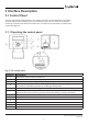
3 Interface Description 3.1 Control Panel Topvex FC The SCP control panel is delivered with a 10 m cable (up to 100 m can be used) that is connected to the panel and with a fast coupling contact, connected to the VSC unit. The contact is connected to the Corrigo controller in the electrical connection box. The cable can be unscrewed in the back of the control panel (figure 3). Compact Air Handling Unit 3.1.1 Operating the control panel Fig.
3.1.1 Operating the control panel Topvex FC The start display (the display normally shown) is at the root of the menu tree. Pressing DOWN will move you through the menu options. UP will move you back through the options. To enter a higher menu level, use UP or DOWN to place the cursor at the menu you wish to access and press RIGHT. If you have sufficient log on privileges the display will change to the menu you have chosen.
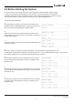
4.2 Before Starting the System Topvex FC On the first start-up, the controller will start a special program for setting language, supply air temp set point, Time & date and week schedule for normal speed. Use the “OK” button to move between changeable parameters and the UP/DOWN arrows to see the displayed alternatives. Confirm by pressing “OK” once more. Move on down in the menu structure by use of the UP/DOWN arrows.
8 Select language by pressing “OK” and then move between the alternatives with the UP/DOWN buttons. Confirm by pressing “OK”. Move to the next level by pressing the “DOWN” button. Topvex FC Compact Air Handling Unit 9 Select “Yes” or “No” After finishing the setup the menu system for “Operator level” will be available. See below menu overviews that display the available menus in the Operator level followed by the “Service level” manual. To enter Service level use code 2222 in the “Access rights” menu.
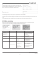
Main menu item Sub-menu item 1 Sub-menu item 2 Explanations Heating: Water Topvex FC Exchanger: Plate/Rot.exc Cooling: Not connect Type of heating selected. Type of exchanger selected. Type of cooling selected. Compact Air Handling Unit Free cool active:No Status of the free cooling function. Support control Active: No CO2/VOC active Never Status of the support control function. Status of the demand ventilation (CO2/VOC) function.
Main menu item Sub-menu item 1 Sub-menu item 2 Explanations →Temperature Extract air temp Actual: ºC Setp: 22.0ºC Topvex FC Configured temperature control (default is Extract air temp). Actual temperature in the chosen control mode. Temperature for the chosen control mode. Compact Air Handling Unit If cascade control Max/min supply setp. Max: 30ºC Min: 14.0ºC Outdoor temp: ºC Supply air temp Act.: ºC Setp: 18ºC Frost protection Actual: ºC Neutral zone 0.
Main menu item Sub-menu item 1 Sub-menu item 2 Explanations Frequency control manual SAF Output: % Topvex FC Frequency control manual SAF Compact Air Handling Unit Output 1/1: 75% Output 1/2: 50% Outdoor comp.output. –20°C = 0 m³/h 0°C = 0 m³/h Act. Comp: 0 m³/h Frequency control manual EAF Output: % Frequency control manual EAF Output 1/1: 75% Output 1/2: 50% Outdoor comp.output. –20°C = 0 m³/h 0°C = 0 m³/h Act. Comp: 0 m³/h Airflow for the supply air fan (constant airflow control).
Main menu item Sub-menu item 1 Sub-menu item 2 Explanations Topvex FC Outdoor comp.Setp. –20°C = 0 m³/h 0°C = 0 m³/h Act. Comp: 0 m³/h Set the SAF airflow compensation for the settable outdoor temperature. The outdoor compensation is linear and is set using two parameter pairs which give the value of the compensation at two different outdoor temperatures. The compensation can be positive or negative. Shows the actual airflow compensation. Compact Air Handling Unit Flow control EAF Actual: xxx m³/h Setp.
Main menu item Sub-menu item 1 Sub-menu item 2 Explanations Topvex FC Outdoor comp.Setp. 1 —20°C = 0 Pa 10°C = 0 Pa Act. Comp: 0 Pa Set the SAF pressure compensation for the settable outdoor temperature. The outdoor compensation is linear and is set using two parameter pairs which give the value of the compensation at two different outdoor temperatures. The compensation can be positive or negative. Shows the actual pressure compensation.
Main menu item Sub-menu item 1 Sub-menu item 2 Explanations Normal Speed Monday Per 1: 07:00–16:00 Per 2: 00:00–00:00→ Topvex FC → Timer Normal Speed Set week schedule Monday to Sunday, Monday-Friday+ Holiday for normal speed. Possible to set 2 periods per day. Note the settings in the commissioning record.
Main menu item Sub-menu item 1 Sub-menu item 2 Explanations Topvex FC → Manual/Auto In this menu the running mode of all the configured output signals and a number of control functions can be manually controlled. The supply air controller‘s output signal can be manually set (Manual/Auto) to any value between 0 and 100%. The temperature output signals will change accordingly if they are in Auto mode. It is also possible to manually control each of the temperature output signals individually.
Main menu item Sub-menu item 1 Sub-menu item 2 Explanations Topvex FC Cooling Auto Manual set: 0.
Main menu item Sub-menu item 1 Sub-menu item 2 Explanations → Control temp Supply air control P-band: 33.0°C I-time: 100.0 sec Topvex FC Set P-band and I-time for the Supply air control function Note: See Corrigo E ventilation manual for more information. Compact Air Handling Unit Extract air control P-band: 100.0°C I-time: 300.0 sec Shutdown mode P-band: 100.0°C I-time: 100.
Main menu item Sub-menu item 1 Sub-menu item 2 Explanations Flow control SAF P-band: 10000.0 m³/h I-time: 10.0 sec Min. output: 0% Set P-band, I-time and Min. output for the supply air fan when the unit comes configured as Flow control from factory. Alternatively Pressure control if that configuration is chosen Flow control EAF P-band: 10000.0 m³/h I-time: 10.0 sec Min. output: 0% Set P-band, I-time and Min. output for the supply air fan when the unit comes configured as Flow control from factory.
Main menu item Sub-menu item 1 Sub-menu item 2 Explanations Topvex FC Control function Mode: Cascade extract ctrl → Control function Set type of temperature control function you want the unit to operate under. Choose between: Room control, Cascade extract ctrl, Outd comp room, Outd comp extr air, Supply air control, Outdoor comp. supply Compact Air Handling Unit Extract/supply air →(possible to switch between the two depending on outdoor temp.
Main menu item Sub-menu item 1 Sub-menu item 2 Explanations Topvex FC Set the upper outdoor night temperature limit for the activation of the free cooling function. Outd. temp night High: 15.0°C Low: 5.0°C Set the lower outdoor night temperature limit for the activation of the free cooling function. Room temp min. 18°C Set the lower room temperature limit. The temperature needs to be above this value for the free cooling function to stay active. If no room sensor are connected extract air is valid.
Main menu item Sub-menu item 1 Sub-menu item 2 Explanations Topvex FC CO2/VOC active Never Type: Fan Min. time: 60 min In applications with varying occupancy the fan speeds can be controlled by the air quality as measured by a CO2/VOC-sensor. See Corrigo manual for further explanation Compact Air Handling Unit → CO2/VOC Control Set active to Never, Always or If time channel off. Set what should be regulated. Select type Fan Set the min.
Main menu item Sub-menu item 1 Sub-menu item 2 Explanations Topvex FC Bypass: On Stop deicing: On Activation temp: 0,0° C Stop temp SAF: -8,0° C This sections is for units with counterflow and crossflow exchangers. Exchanger deicing allowed with bypass, On/Off. Exchanger deicing allowed with stop of the supply air fan (SAF), On/Off Outdoor temperature limit to allow deicing function. Outdoor temperature limit for forced stop deicing, interlock of bypass deicing.
Main menu item Sub-menu item 1 Sub-menu item 2 Explanations → Communication Function Port1 Slave Function Expansion unit Slave Topvex FC Choose between different communications Slave, Expansion unit, Frequency converter, External display, Exp and freq conv or Exp and ext display. → Function Port2 Expansion unit Compact Air Handling Unit PDTxxC-2 Pressure dual transmitter module.
4.4 Free cooling description is function is used during the warm period to save energy by using cold outdoor air, e.g. during night time, to cool down the building. Topvex FC Note: The following is only valid if the free cooling function is set to Active in the program menu. Compact Air Handling Unit Free cooling is only activated when the following starting conditions are met.
5 Maintenance 5.1 Important Danger • • Topvex FC Compact Air Handling Unit Make sure that the Mains supply to the unit is disconnected before performing any maintenance or electrical work! All electrical connections must be carried out by an authorized installer and in accordance with local rules and regulations. Warning • • Although the Mains supply to the unit has been disconnected there is still risk for injury due to rotating parts that have not come to a complete standstill.
5.3 Maintenance instructions 5.3.1 Open the doors Topvex FC The side hatch is opened by unscrewing 5 screws (figure 4.) Lower the door carefully. Compact Air Handling Unit Fig.
5.3.2 Changing Supply/Extract air filter Topvex FC The filter cannot be cleaned and must be changed when necessary. New filters can be ordered from Systemair. Operation time between filter changes depends on the air pollution at the installation site. A differential pressure switch indicates when it’s time to change the filters. This will trigger an alarm in the control panel. Compact Air Handling Unit When this occurs do the following: 1. Replace the filters with new ones as described below. 2.
5.3.3 Checking the heat exchanger Topvex FC After a long time of use dust may build up in the exchanger and block the airflow. It is important to clean the exchanger regularly (once a year) to maintain high efficiency. The heat exchanger can be taken out of the unit for maintenance (figure 6). Compact Danger • • • Air Handling Unit Risk of personal injury! The heat exchanger is heavy. There is a risk that the heat exchanger falls out of the unit.
5.3.4 Checking the fans Topvex FC Even if the required maintenance, such as change of filters is carried out, dust and grease may slowly build up inside the fans. This will reduce the efficiency. The fans are easily taken out from the unit (figure 7) by loosening 4 screws and disconnecting the fast couplings to the electric wires. Depending on the accessories installed, remove the tubing next to the fast couplings for the extract air fan or both the extract air fan and supply air fan.
5.3.8 Changing the Internal Battery Note: This procedure requires knowledge of proper ESD protection; i.e. an earthed wristband must be used! Topvex FC When the alarm ”Internal Battery” is activated and the battery LED lights up red, the battery for backup of program memory and real-time clock has become too weak. The battery is replaced as described below. A backup capacitor saves the memory and keeps the clock running for at least 10 minutes after the power supply is removed.
6 Troubleshooting Note: Should problems occur, please check or correct the following before contacting your service representative. Always check if there are any alarms active in the control panel. Topvex FC 1. Fan(s) do not start • Check if there are any alarm messages • Check that the fuses are not defect (pos.9 figure 2) • Check the settings in the control panel (times, week schedule, auto/manual operation etc.) 2.
7 Service Before calling your service representative, make a note of the specification and production number from the type label (figure 8) Topvex FC 1 Compact Air Handling Unit Fig.
Topvex FC Compact Air Handling Unit Operation and Maintenance Instructions Operation and Maintenance Instructions Document in original 35 language 125918-EN_GBSystemair AB 2015-03-16 A001
Systemair AB reserves the right to make changes and improvements to the contents of this manual without prior notice. Systemair AB Unit 28, Gravelly Industrial Park, Birmingham, B24 8HZ Tel: +44 (0) 121 322 0200 Fax: +44 (0) 121 322 0201 Emal: info@systemair.co.