
VSC OPERATION AND MAINTENANCE INSTRUCTIONS 4 118 0324 2 IOM

5
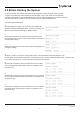
Topvex FC
Compact Air Handling Unit
Operation and Maintenance Instructions
Document in original language
125918-EN_GB
2015-03-16 A001
Operation and Maintenance Instructions
Systemair AB
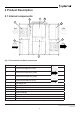
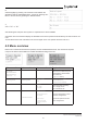
2.2 Description of internal components
2.2.1 Supply and Extract air Fans
The fans have external rotor motors of EC type which are steplessly controlled individually by setting the
control signal to a xed value. It is possible to program the speed in 2 steps (normal/reduced) depending
on the programming of the week schedule. The motor bearings are life time lubricated and maintenance
free. It is possible to remove the fans for cleaning, see chapter 5 for more information.
2.2.2 Supply and Extract air Filters
The lters F7 (ePM 2,5 65%) for the supply air lter and M5 (ePM 10 70%) for the extract air lter.
The lters need to be replaced when polluted. New lters can be acquired from your installer or wholesaler.
2.2.2.1 Pressure guard for lters
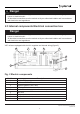
A pressure guard measures the dierential pressure over the supply and extract air lters (pos. 10 gure 1.
When the pressure drop reaches the set value an alarm is triggered in the main regulator. The dierential
pressure can be set between 40 and 300 Pa. The pressure switch is preset from factory to 240 Pa.
2.2.3 Heat Exchanger
VSC models are equipped with a counter ow heat exchanger and a by-pass damper. The operation
of the by-pass damper is automatic and depends on the set temperature or if deicing is in operation.
The heat exchanger is removable for cleaning and maintenance, see chapter 5 for more information.
2.2.4 Temperature sensor
4 temperature sensors (PT1000) are included in the unit from factory. The sensors are as follows:
• Supply air sensor
• Extract air temperature sensor
• Outdoor air temperature sensor
In VSC all temperature sensors are mounted and wired inside the unit.
2.2.5 Water heating battery
In units with built in water heating battery. The coil material is copper piping with a frame of galvanized sheet steel and
aluminium ns. The coil is equipped with sensor for frost protection.
2.2.6 Electrical Heater
In units with built in electrical heater the heating rods are located before the supply air fan in the airow
direction. The electrical heating battery has both automatic and manual overheating protection. The manual overheat
protection is reset by pushing the reset button on top of the electrical heater frame (pos. 8 gure 1). The power de-
mand of the electric heating coil is controlled by the main regulator, which controls the heat steplessly by a SSR relay
control according to the selected control function that is set in the control panel.