
VSC OPERATION AND MAINTENANCE INSTRUCTIONS 4 118 0324 2 IOM

7
Topvex FC
Compact Air Handling Unit
Operation and Maintenance Instructions
Document in original language
125918-EN_GB
2015-03-16 A001
Operation and Maintenance Instructions
Systemair AB
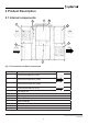
3 Interface Description
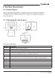
3.1 Control Panel
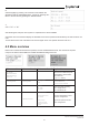
The SCP control panel is delivered with a 10 m cable (up to 100 m can be used) that is connected to
the panel and with a fast coupling contact, connected to the VSC unit. The contact is connected to
the Corrigo controller in the electrical connection box. The cable can be unscrewed in the back of the
control panel (gure 3).
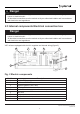
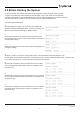
3.1.1 Operating the control panel
Fig. 3 The control panel
Position Explanation
1
Alarm button: Gives access to the alarm list.
2
Alarm LED: Indicates alarm by ashing red light.
3
Write LED: Indicates by ashing yellow light that parameters can be set or changed.
4
OK button: Press this button to be able to change or set parameters whenever possible. Also used to
move between changeable parameters in one dialogue window frame.
5
Cancel button: Used to abort a change and return to the initial setting.
6
Right/Left & Up/Down buttons: Used to move up, down, left & right in the menu tree. Up/Down
buttons are also used to increase or decrease values when setting or changing parameters.
7
Mounting holes.
8
Connection block.
9
Connection to brown cable.
10
Connection to yellow cable.
11
Connection to white cable.
12
Connection to black cable.