VTR 100/B LITE User Manual Document in original language | 212961 · 01 GB
© Copyright Systemair AB All rights reserved E&OE Systemair AB reserves the rights to alter their products without notice. This also applies to products already ordered, as long as it does not affect the previously agreed specifications.
Contents 1 2 3 4 Overview ......................................................1 1.1 General Description ................................1 1.2 Warranty ..............................................1 1.3 Type label.............................................1 1.4 Important Safety Information ....................1 1.4.1 Intended Use.............................1 1.4.2 Admonitions .............................2 1.4.3 Declaration of Conformity ............3 Configuration ................................
Overview | 1 Overview 1.1 General Description This manual describes basic information how to operate and perform maintenance on the unit and the system it is connected to. Read the instructions carefully and in its entirety. For description of advanced settings and installation of accessories see Service and Accessories Installation manual. All documents can be found in our online catalogue at . 1.
2 | Overview • The device is not to be used by persons (including children) with reduced physical, sensory or mental capabilities, or lack of experience and knowledge, unless they have been given supervision or instruction. • The system should operate continuously, and only be stopped for maintenance/service. • Do not connect tumble dryers to the ventilation system. • Make sure that filters are mounted before starting the unit. 1.4.
Overview | 1.4.3 Declaration of Conformity Manufacturer Systemair UAB Linų st. 101 LT–20174 Ukmergė, LITHUANIA Office: +370 340 60165 Fax: +370 340 60166 www.systemair.com hereby confirms that the following product: Heat recovery ventilation unit: VTR 100/B LITE (The declaration applies only to product in the condition it was delivered in and installed in the facility in accordance with the included installation instructions.
4 | Configuration 2 Configuration 2.1 Control panel Connect the unit electrically to the mains with the enclosed plug and check that it starts up correctly. The control panel is used to make the necessary adjustments. An external control panel can be connected on the top of the unit. The illustration below shows the control panel with a short description. 1 3 2 4 Fig.
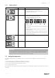
Configuration | 2.1.1 Display symbols Symbol 19 °C Description Explanation Temp Illustrates the current set-point for supply air temperature (from completely empty to filled symbol). Turn the SELECTION knob to choose temperature. Press ENTER to save the setting. Airflow Illustrates the current airflow. The airflow can be set manually in 5 steps: Off, Low, Nom, High and Auto. Turn the SELECTION knob to choose airflow. Press ENTER to save the setting. Temp Airflow A. Ventilation off. 1 B.
6 | Configuration 19 °C Temp An unfilled temperature symbol will activate manual summer mode. See chapter 2.5 2.3 Manual setting of airflow It is possible, at any time, to manually set the airflow in the main menu display. By choosing the fan symbol and confirming, it is possible to increase or decrease the airflow in 5 steps: Off, Low, Nom, High and Auto. By doing so, you override the programmed week schedule for the unit until the end of the present time period in the week program (chapter 2.4).
Maintenance | 7. Set which airflow the fan is supposed to be running in the ON level, choose between Low, Nom, High or Auto. Set which airflow the fan is supposed to be running in the OFF level, choose between OFF, Low, Nom or High. Airflow On level: low/nom/high/auto Off level: off/low/nom/high Note: If an electrical re-heater battery is installed and active and the unit is shut down from the control panel, for example by choosing OFF.
8 | Maintenance Task 6 months Heat exchanger cleaning 1 year 3 years When necessary X X Belt replacement X Checking and cleaning louvres/ diffusers X Checking and cleaning outdoor air intake X Checking and cleaning roof cowl (if fitted) X X1 Cleaning of duct system 1. It is recommended to do this every 5 years and is normally carried out by authorized companies specialized in this area. • Use original spare parts from only. • Scan QR code on the type label to find a spare part list. 3.
Maintenance | When it’s time to change the filters an alarm is shown on the control panel display. When this occurs do the following: 1. Stop the unit by disconnecting the mains. 2. Open the front hatch. See chapter 3.2. 3. Remove old filters and insert new ones. Make sure filters are not mixed up during the replacement process. Supply and extract air filters may be different. 4. Close and lock the front hatch and connect the unit to mains. 5. Reset the filter time as described below (chapter 3.3.1).
10 | Maintenance 1 Disconnect the rotor power supply and the rotor sensor. The cables are found beside the rotor at the back. 2 Pull out the rotor towards you. Some force may be needed. 3 Clean the rotor. Wash in hot soapy water. Do not use detergent containing ammonia. Rinse using, for instance, a shower handle. Warning Ensure the rotor motor is not exposed to moisture 3.
Trouble shooting | 3.6.4 Checking and cleaning the duct system Dust and grease deposits may build up in the duct system, even if required maintenance such as changing of filters is being carried out. This will reduce the efficiency of the installation. The duct runs should therefore be cleaned/changed when necessary. Steel ducts can be cleaned by pulling a brush soaked in hot soapy water through the duct via diffuser/louvre openings or special inspection hatches in the duct system (if fitted).
12 | Trouble shooting Alarm Explanation Do the following Low SS Indicates low supply air temperature The alarm is displayed in the control panel. If water reheater is configured and frost protection have failed, then an extra security function is triggered when supply air temperature is lower than 5 °C and outdoor air temperature is below 0 °C. RH Indicates malfunction of internal relative humidity sensor. The alarm is displayed in the control panel.
212961 | 01
Phone +370 340 60165 Fax +370 340 60166 www.systemair.com VTR 100/B LITE · User Manual · 212961 · en_GB · 190924 · 01 Systemair UAB Linų st.