Air Handling Unit Topvex SC, TC Operation and Maintenance Instructions Document in original language | 214959 · A007 GB
© Copyright Systemair AB All rights reserved E&OE Systemair AB reserves the rights to alter their products without notice. This also applies to products already ordered, as long as it does not affect the previously agreed specifications.
Contents 1 2 3 4 5 6 7 Overview ......................................................1 1.1 Intended use .........................................1 1.2 Disclaimer ............................................1 1.3 Warranty ..............................................1 Warnings.......................................................1 Warnings signs on product ................................2 Product description..........................................3 4.1 Supply and extract air fans .................
Overview | 1 Overview This manual includes the information required. If other accessories not included at delivery are in use, read their separate instructions. The key to proper and safe operating is to read this manual thoroughly, use the air handling unit according to given guidelines and follow all safety requirements. 1.1 Intended use The air handling units are intended to provide ventilation and depending on settings, heat recovery, air heating or free cooling.
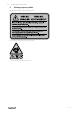
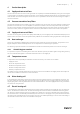
2 | Warnings signs on product 3 Warnings signs on product Warning signs located on the air handling units. Fig. 1 Disconnect all supply circuits before access to terminals Fig.
Product description | 4 Product description 4.1 Supply and extract air fans The fans have external rotor motors of EC type which are steplessly controlled individually by setting the control signal to a fixed value. It is possible to program the speed in 3 steps (high/normal/low) depending on the programming of the week schedule. The motor bearings are maintenance free. It is possible to remove the fans for cleaning, see chapter 7 for more information. 4.
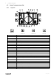
4 | Product description 4.8 Internal components position 4.8.1 Topvex SC Fig.
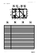
Product description | 4.8.2 Topvex TC Fig.
6 | Product description 4.9 Access control cabinet Danger Disconnect the mains power supply to the unit before moving the Access control cabinet or opening the lid. Warning Before obtaining access to terminals, all supply circuits must be disconnected. Access control cabinet is mounted on top of the unit. It is possible to remove the cabinet and mount it in a suitable location, a control cabinet kit is available as an accessory. The enclosure class for Access control cabinet is IP44.
Start up | 5 Start up Read and follow carefully the installations instruction before start up. Before stating up the unit check following points with power supply off. • Check so the unit is placed horizontally • Check inside the unit and secure that the unit is clean • Check that all transport protection is removed • Turn on the power supply 5.1 NaviPad NaviPad is Systemair's user interface with a 7” capacitive touch screen.
8 | Start up 5.1.1 Start-up wizard At the first start up of NaviPad you need to calibrate the screen by pressing lightly on the cross marks. Then you will be requested to fill in following information: • Language • Time & Date Available air handling units will be shown in the device list. Choose the air handling unit you want to pair with your NaviPad. Use CU27 control unit’s serial number in the air handling unit to be sure to pair the correct air handling unit with NaviPad.
Start up | 5.1.2 Home page Menus and functions may differ depending on actual configuration and/or application version running in the air handling unit. Unit name 2022–02–04 Running mode Outdoor Supply Normal speed 31.3 °C 16.1 °C Setpoint adjustment Extended run 120 min -2°C 0 +2°C Screen image: The home page shows an overview of the air handling unit operation status. 5.1.
10 | Start up 5.1.5 User levels 5.1.6 End user When logged out Read /write privileges — Home page Possible actions in end user mode are to stop the air handling unit for maintenance (e.g. filter exchange), change the time for extended run and change the temperature setpoint. Flow diagram and active alarms in alarm list are visible. Operator mode — log in with 1111 Logged in Read and write privileges (except Configuration). Acknowledge/block/unblock alarms and view the alarm history.
Operation | 6 Operation 6.1 Controller settings Menus and functions may differ depending on actual configuration and/or application version running in the air handling unit. 6.1.1 Data & Settings Data & Settings 2022–02–04 Operation overview > In-/Output status > Energy insight > Temperature control > Fan control > Demand control > Fire/Smoke > Filter monitoring > Alarm list > 6.1.1.1 Operation overview Value of active signals I/O signals and operation mode.
12 | Operation 6.1.1.2 In- and output status I/O status Total overview of: • Sensors • I/O • Fan control • Temperature sequencing • Running mode • Device status All can be controlled in manual mode. • Manual setting of temperature sensor • Locking of fans at adjustment • Manually I/O testing of external functions • Raw values 6.1.1.3 Energy insight Logs and presents energy data: • Energy usage and SFP for fans • Recovered energy for exchanger 6.1.1.4 Temperature control Settings for temperature.
Operation | 6.1.1.5 Fan control Settings for fan control. • Setpoint for different fan speed • Fan compensation e.g. outdoor compensated fan curves • Start delay of fans, shut of dampers etc. • SFP menu • External fans 6.1.1.6 Demand control Settings for: • Air quality control (CO2/RH) • Recirculation • Support control • Free cooling 6.1.1.7 Fire/Smoke Settings for: • Fire dampers • Smoke detector status • Fire damper test 6.1.1.
14 | Operation 6.1.2 Flow chart Flow diagram 2022–02–04 18 000 m³/h 34 Pa -6,8 °C 22,1 °C 198 Pa 71 % Open 32 % RH 22,1 °C 84 % h 71 % RH -12,2 °C 54 Pa 18 000 m³/h 21,8 °C 25 % RH 19,9 °C 199 Pa 16,7 °C 100 % 74 % ON Open OFF 42 % 0% Dynamic flow chart of current configured air handling unit. Active sensors and components are visible with values shown in real time. When pressing on values or items marked in blue you will be forwarded to related settings and/or overview page. 6.1.
Operation | 6.1.4 Time Settings In this menu date and time can be changed as well as other system settings. Settings for: • Date and time • Schedule for operating time (Example 2 & 3) • Schedule for holiday • Schedule for extra time groups Each day has up to two individual running periods, set desired start and stop time. For holidays, set the dates in Time settings > Schedule > Holiday calendar and the time in Time settings > Schedule > Fan Low Speed/Fan Normal Speed/High Speed.
16 | Operation 6.1.5 Configuration • System settings • Configuration wizard (Example 4) • Function configuration (Example 5) • I/O allocation settings • Alarm configuration (Example 6) • PID controllers The configuration wizard is a menu that simplify the procedure to Activate and Configure common accessories and functions and Allocate it’s in- and outputs. The wizard makes necessary configurations automatically and guide the user through limited options.
Operation | Example 6: Alarm configuration Configuration > Alarms 2022–02–04 Alarm delay at start up 60 s Filter alarm supply air Search alarm no: 53 > Air and temperature control > Extra functions > Extra sensors and alarms > Fire/Smoke > Component malfunction > Manual operation and warnings > Configuration > ... > Filter alarm supply air Action: Class B Delay: 300 s Name: Original name: 6.1.
18 | Operation 6.2 Advanced HMI (Human Machine Interface) Settings Return to system overview dashboard by pressing on the NaviPad button,. Go to Advanced HMI settings.
Operation | Example 9: Restore NaviPad factory settings You will be requested to confirm your action. All settings including password will be reset and Start-Up wizard will run again. 6.3 No communication 2022–02–04 Home > Available devices Unit name No Communication If the above symbol are shown the communication to the selected air handling unit is lost. One reason could be that the IP number has changed.
20 | Maintenance 7 Maintenance Danger • Disconnect the mains power supply to the unit is before performing any maintenance or electrical work! • Carry out all electrical connections in accordance with local rules and regulation. Electrical connections must be carried out by an authorized installer. Warning • Be aware of rotating parts even if the mains power supply is disconnected • Beware of sharp edges during mounting and maintenance. Use protective clothing.
Maintenance | 7.2 How to replace supply/extract air filter The bag filter must be changed when necessary, they cannot be cleaned. We recommend ordering original filters from Systemair. Operation time between filter changes depends on the air quality. A differential pressure transmitter indicates when it is time to change the filters, which will trigger an alarm in NaviPad. 1. Pull out the old filters and replace with new ones. 2. In NaviPad, log in as operator; 1111 (min. level). 3.
22 | Maintenance 7.5 How to clean the fans Caution • Do not use water! Clean the fans with a cloth or a soft brush. Use white spirit to remove obstinate settlements. Allow drying properly. It is possible to remove the fan for cleaning. For Topvex SC35 the door beam has to be removed, figure 10. 1. Disconnect the fast coupling to the electric wire 2. Disconnect the blue and red tubes from the supply air fan (standard units with CAV).
Maintenance | 7.7 How to clean the electric heating coil Clean the heating rods with compressed air, vacuum or a brush. Remove the fan for access, see chapter 7.5. 7.8 How to clean the extract air louvres and inlet diffusers Remove diffusers and louvres and wash in hot soapy water when necessary. Remount them with their original settings and positions in order not to unbalance the system. 7.9 Clean the outdoor air intake Clean the air intake grille once a year. 7.
24 | Maintenance 7.11 Where to reset tripped fuses Possible to reset the fuses without opening the hatch to the compartment. 2 1 3 Fig. 7 Position Description 1 Automatic fuse 1~ (Controls only) 2 Automatic fuse 3~ (Fans only) 3 Automatic fuse 3~ (EL heater only) 7.12 How to reset the manual overheat protection (EL units) Push the red button on the electrical heater, figure 8, (1). Possible to reset overheat protection for electric heating coil without opening the hatch to the compartment.
Maintenance | 7.13 How to replace the fan module When ordering a replacement fan module, note if it is supply or extract fan. This is important for the fan to get the correct Modbus address. For size Topvex SC35 the door beam has to be removed, figure 10. 1. Disconnect the fast coupling to the electric wire 2. Disconnect the blue and red tubes from the supply air fan (standard units with CAV).
26 | Maintenance 7.14 How to replace the heat exchanger Remove the doors 1. Remove the cover over the hinges with a screwdriver. 2. Remove the hinge pins 3. Remove the doors on front and back side. Remove damper Warning Beware of sharp edges. Use gloves and protective clothing. 4. Loosen the bolts holding the damper rails. Remove the damper rails. 5. Rotate the damper and lift in the direction away from the exchanger. 6. Lift the damper out from the middle section.
Maintenance | Remove the door beam 8. Loosen the screw on the front door beam (6 screws) and remove the beam. Fig.
28 | Maintenance Replace the exchanger Caution • Handle the heat exchanger with care. • The heat exchanger is heavy. 9. Push the exchanger out. 10.Remove the old exchanger. 11.Place the new exchanger carefully in the opening and push gently in place. Fasten the door beam 12.Fasten the door beams (6 screws on front and 6 screws on the back). Fasten the rail holding the exchanger 13.Fasten the bolts holding the rail on the opposite side of the partition wall.
Maintenance | Fasten the damper 14.Insert the damper in the area above the exchanger. Caution Do not drag the damper on the exchanger. 15.Lift the damper with the short end on the rail at the outer beams. Observe the small hooks to secure the damper. 16.Fasten the damper by fastening the damper rails with the bolts. Mount the doors 17.Place the doors in position. 18.Unite the hinges and replace the pin.
30 | Maintenance 7.15 Change the internal battery in control unit CU27–C The alarm text Internal battery error is shown in NaviPad when it is time to change the battery. Expected life time of battery is 5 years. Caution ESD protection; i.e. an earthed wristband must be used! Note: Note the cable connectors positions before disconnecting them. Disconnect all the wired cable connectors (1) from control unit CU27–C.
Troubleshooting | 8 Troubleshooting Check or correct the following before contacting your service representative. Always check if there are any alarms active in the control panel (chapter 9). 1. Fan(s) do not start • Check if there are any alarm messages. • Check the settings in the control panel (times, week schedule, auto/manual operation etc.). • Check if the fuses has tripped. 2. Reduced airflow • Check if there are any alarm messages. • Check the settings for normal and low fan speed.
32 | Alarms 9 Alarms A LED-light in the NaviPad button indicate the status of the air handling unit. • Fixed green — Status ok (no active alarms). • Flashing red — Active/returned alarms in one or several air handling units or lost connection with an air handling unit. • Fixed red — Acknowledged/blocked alarms in one or several air handling units, alarms not reset.
Service | 10 Service Before calling your service representative, make a note of the specification and production number from the type label (figure 13) Fig. 13 Type label Position 11 Description 1 Item number 2 Production order number 3 Consecutive number 4 Production date 5 Product code (product specification) 6 Scannable code (spare parts, documentation) General conditions 11.1 Standard tools If handles are misplaced; open the doors with a 16 mm wrench. 11.
Phone +46 222 440 00 www.systemair.