Original instructions IHC EN .... 7 SE .... 9 ES .... 22 NL .... 25 FI .... 38 DK .... 41 NO .... 12 IT .... 28 FR .... 15 DE .... 18 PL .... 31 RU ....
IHC EN The introduction pages consist mainly of pictures. For translation of the English texts used, see the respective language pages. SE Introduktionssidorna består huvudsakligen av bilder. För översättning av de engelska texter som används, se respektive språksidor. NO Introduksjonssidene består hovedsakelig av bilder. For oversettelse av de engelske tekstene, se de respektive språksidene. FR Les pages de présentation contiennent principalement des images.
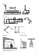
IHC Dimensions 160 77 147 0,9 500/676 169 Wall bracket 35 18 25,5 ø8 17,5 46,5 60 24 115 8 23 107 31 IHE (18050) 19 Positioning 160 Installation height 1,8–2,5 m 2,3–3,5 m Fig.
IHC Minimum mounting distance IHE ceiling bracket 180 200 160 300 min 30° 1000 Flammable material 1800 Replacing the lamp 1 1 3 3 4 5 4 2 500
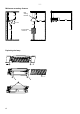
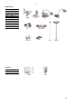
IHC Accessories 11884 IHUB* 18050 IHE 16975 IHXH* 16976 IHXL* 11887 IHT* 16974 IHTW* 16970 IHP* 92865 KLS1KS 93272 IHAF 220648 IHC1200 220649 IHC1800 *) See separate manual. IHUB IHT KLS1KS IHE IHXH IHXL IHT+IHTW IHAF IHP IHP+IHT Controls 92867 IHBD3* 10740 CBT *) See separate manual.
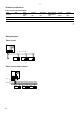
IHC Technical specifications Carbon infrared heater IHC (IP44) Item number Type Voltage Amperage IHC12 Heat output [W] 1150 19603 19604 [V] 230V~ IHC18 1750 230V~ Wiring diagrams Timer control CBT L N 1 2 3 Max load 3500W IH/IHC 230V~ L N IH/IHC L N IH/IHC L N Timer control with contactor CBT L N 230V~ 1 2 3 L N L1 400V3~ L2 L3 N IH/IHC 6 L N IH/IHC L N IH/IHC L N Length Weight [A] 5,0 Max.
IHC EN Installation and operating instructions General Instructions Read these instructions carefully prior to installation and use. Keep this manual for future reference. The product may only be used as set out in the assembly and operating instructions. The guarantee is only valid should the product be used in the manner intended and in accordance with the instructions.
EN IHC 9. Fit the new lamp. Note do not touch the lamp with your fingers, wear gloves or the like. 10.The protective tube must be refitted to the cables, so that the cables are not damaged when the grille is fitted. 11.Reassemble the unit again. See the introduction pages. Maintenance The power supply to the unit must be disconnected during all service, repair and maintenance work. Wait until the unit is cold.
Tel: +46 31 336 86 00 mailbox@frico.se www.frico.net For latest updated information and information about your local contact: www.frico.