VDD Vibration Diagnostic Device User Manual Document in original language | · 003 GB
© Copyright Systemair AB All rights reserved E&OE Systemair AB reserves the rights to alter their products without notice. This also applies to products already ordered, as long as it does not affect the previously agreed specifications.
Contents 1 General information .........................................1 1.1 Notice symbols ......................................1 1.1.1 Instruction symbols.....................1 2 Important safety information .............................1 3 Warranty .......................................................1 4 Extension of maintenance intervals .....................1 5 Description ....................................................2 5.1 Intended use .........................................2 5.
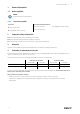
General information | 1 General information 1.1 Notice symbols Note: Useful information and instructions 1.1.1 Instruction symbols Instruction Instruction with fixed sequence ♦ Carry out this action 1. Carry out this action 2. Carry out this action ♦ (if applicable, further actions) 2 3. (if applicable, further actions) Important safety information ♦ Read the operating instructions completely and carefully. ♦ Observe and respect local conditions, regulations and laws.
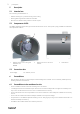
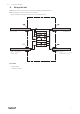
2 | Description 5 Description 5.1 Intended use Fan monitoring and visualisation of • Vibration velocity (Vrms) of motor bearing and fan casing. • Warning/alarm signal if limit values are exceeded. • Record of the vibration history values for the last 3 years. 5.2 Components of VDD The VDD is completely parametrised, pre-wired and mounted on the fan. This system is (only) available in combination with a Systemair Axial fan. 2 1 1 3 3 1 5.
Limit values | 7 Limit values Limit values for in situ operation adjusted for the VDD. These values were evaluated under consideration of ISO 14694:2003 (Industrial fans - Specifications for balance quality and vibration levels). Fans < 75 kW (BV–3) Limit to warning [mm/s] Limit to alarm [mm/s] Motor 6.3 92 Casing 11.8 2 12.5 2 Limit to warning [mm/s] Limit to alarm [mm/s] Motor 4.5 7.1 1 Casing 92 1 Fans > 75 kW (BV-4) 1 11.
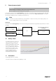
4 | LED display 8 LED display The LED display shows the vibration velocity (rms) of the casing or the motor. According to the adjusted levels (7 Limit values, page 3) the segment display changes the colour (green, yellow, red); the switch-on and switch-off delays or the hysteresis are not considered.
External process signals | 9 External process signals Important External voltage can damage or destroy the sensor/evaluation unit. ♦ Do not apply any external voltage to the terminals. If the vibration values exceed the Warning/Alarm— limits (see 7 Limit values, page 3), the relevant signals “24V Warning” and/or “24V Alarm” (see 12 Wiring of the VDD, page 6) are activated with a delay of 30 seconds. These signals can be used for implementation in a building control system e.g.
6 | Wiring of the VDD 12 Wiring of the VDD ♦ Electrical connection may only be carried out by adequately qualified persons. ♦ Do not apply any external voltage to the terminals. External voltage can damage or destroy the sensor/evaluation unit. VTV122 9,6...
| 003
Tel.: +49 (0)7930/9272-0 Fax: +49 (0)7930/9273-92 info@systemair.de www.systemair.de VDD · User Manual · · en_GB · 2020-12-07 · 003 Systemair GmbH Seehöfer Str.