
L BAL E263
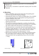
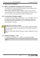
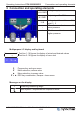
Table Of Contents

5 Electrical installation
5.1 EMC-compatible installation of control lines
Pay attention to maintain sufficient distance from powerlines and
motor wires to prevent interferences.
When using a shielded cable the shield must be connected (as
short and with as low an induction as possible!) to the PE conduc-
tor on one side at the signal input (of the evaluation unit).
5.2 Connection Voltage supply
Connection Voltage supply at terminals: “+U
S
” and “GND”. Here, it
must be strictly observed that the mains voltage lies within the
allowable tolerance specifications (
Technical data and name-
plate affixed to the side).
Danger due to electric current
Only PELV current sources which ensure safe electrical isolation
of the operating voltage in accordance with IEC/DIN EN 60204-1
must be used.
There is no potential isolation between supply voltage and output
signal.
5.3 Output voltage 0 - 10 V
Connection to Terminals “A” - “GND” (I
max
Technical data).
It is not permissible to connect outputs of several devices to each
other!
Operating Instructions PCA1000/6000D2 Electrical installation
L-BAL-E263-GB 1551 Index 001 Part.-No. 00163445-42
8/20