
MANUAL RVK003
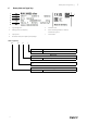


Table Of Contents
- 1 General information
- 2 Important safety information
- 3 Warranty
- 4 Delivery, transport, storage
- 5 Description
- 6 Name plate and type key
- 7 Accessories
- 8 Installation
- 9 Electrical connection
- 10 Commissioning
- 11 Operation
- 12 Troubleshooting/maintenance/repair
- 13 Cleaning
- 14 Deinstallation/dismantling
- 15 Disposal
- 16 Commissioning Report

Electrical connection |
7
Important
Damage to the bearings or other parts of the fan can occur.
♦ Do not place a duct bend directly before or after the fan!
♦ Ensure a smooth and constant air flow to the device.
Important
Damage to the bearings or other parts of the fan
can occur.
♦ Do not place a duct bend directly before or
after the fan!
♦ Ensure a smooth and constant air flow to the
device.
Ø D
min.
2,5x Ø D
min.
2,5x Ø D
• Round duct system: D = Nominal diameter
• Rectangular duct system: D = Hydraulic diameter
8.1 Installation positions
The installation is possible in any mounting position.
8.2 Installation with mounting bracket
Note:
The mounting
bracket is
included with the
delivery.
♦ Mount the mounting
bracket on the fan,
see adjacent image.
9 Electrical connection
Safety information
♦ Observe 2 Important safety information, page 1
♦ Prevent the ingress of water into the connection box.
Connection
♦ Check if the data on the nameplate matches the
connection data.
♦ Complete the electrical connection according to the
circuit diagram.
♦ Connect the cable end in a dry environment.
♦ Install a circuit breaker in the permanent electrical
installation, with a contact opening of at least 3 mm
at each pole.
Protective grounding wire
The protective grounding must have a cross-section equal to or greater than that of the phase conductor.
Residual current circuit breaker
All-current-sensitive residual current circuit breakers are required for use in alternating-current systems with 50/60
Hz, in combination with electronic devices such as EC motors, frequency converters or uninterruptible power supplies
(UPS).
| 003